DAF 95XF. Manual - part 121
6
Description of components
DESCRIPTION OF BRAKE COMPONENTS
1-21
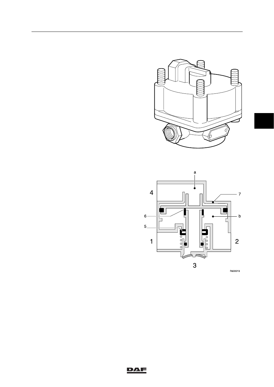
1.11 RELAY VALVE
Purpose
The purpose of the relay valve is to speed up
the reaction time and release speed of the
brakes by minimising the time required for
pressurising and venting the brake chambers.
Models without increase of control pressure
Port (1) is connected to the air reservoir. When
port (4) is pressureless, inlet (5) is closed and
exhaust (6) opened. The brake chambers
connected to port (2) are now vented.
When compressed air passes through port (4)
into chamber (a) above piston (7), the piston is
forced downwards. Exhaust (6) is closed and
inlet (5) opened. The compressed air now
passes from the air reservoir to the brake
chambers.
A state of balance is achieved when the
pressures on both sides of piston (7) are equal.
Then, both inlet and exhaust are closed.
3
ǹ 0006