Chrysler Town, Dodge Caravan. Manual - part 421


  Index      Chrysler     Chrysler TOWN & COUNTRY, VOYAGER, Dodge Caravan - service repair manual 2001-2007 year


Search            


Content   ..  419  420  421  422   ..


Chrysler Town, Dodge Caravan. Manual - part 421


A conventional mechanical interlock system is also

used. This system manually prohibits shifter move-
ment when the ignition switch is in the LOCK or
ACC positions. Solenoid operation is not required in
these key positions.

For intended BTSI system operation, refer to the

following chart:

ACTION

EXPECTED RESPONSE

1. Turn key to the

9

OFF

9

position.

1. Shifter CAN be shifted
out of park with brake
pedal applied.

2. Turn key to the

9

ON/RUN

9

position.

2. Shifter CANNOT be
shifted out of park.

3. Turn key to the

9

ON/RUN

9

position and

depress the brake pedal.

3. Shifter CAN be shifted
out of park.

4. Leave shifter in any
gear and try to return key
to the

9

LOCK

9

or

9

ACC

9

position.

4. Key cannot be
returned to the

9

LOCK

9

or

9

ACC

9

position.

5. Return shifter to

9

PARK

9

and try to remove

the key.

5. Key can be removed
(after returning to

9

LOCK

9

position).

6. With the key removed,
try to shift out of

9

PARK

9

.

6. Shifter cannot be
shifted out of

9

PARK

9

.

NOTE: Any failure to meet these expected
responses requires system adjustment or repair.

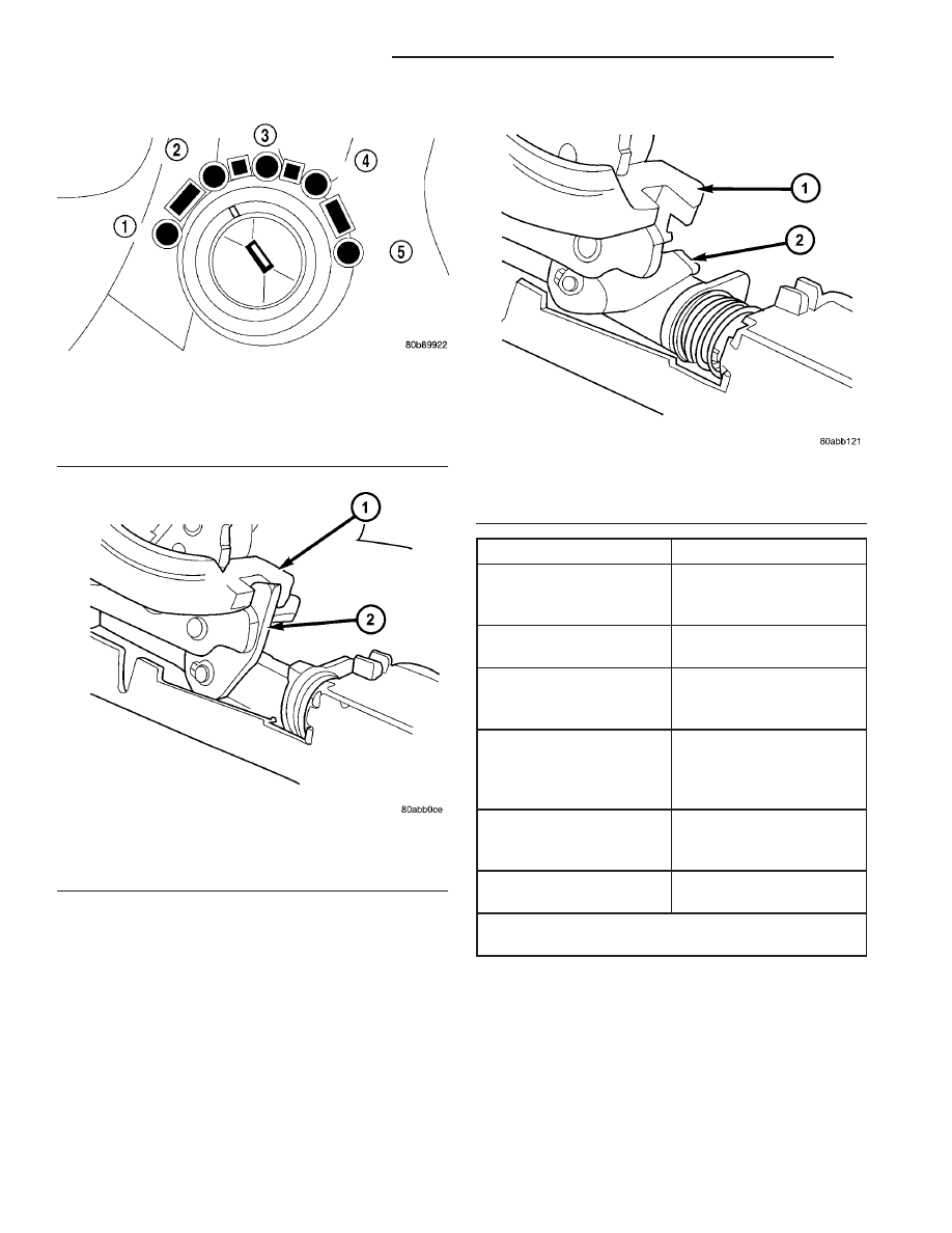
Fig. 293 Ignition Key/Switch Positions

1 - ACC
2 - LOCK
3 - OFF
4 - ON/RUN
5 - START

Fig. 294 Pawl Engaged to Shift Lever

1 - GEAR SHIFT LEVER
2 - GEAR SHIFT LEVER PAWL

Fig. 295 Pawl Disengaged From Shift Lever

1 - GEAR SHIFT LEVER
2 - GEAR SHIFT LEVER PAWL

21 - 234

41TE AUTOMATIC TRANSAXLE

RS

SHIFT INTERLOCK SOLENOID (Continued)

DIAGNOSIS AND TESTING - BRAKE/
TRANSMISSION SHIFT INTERLOCK SOLENOID

For intended BTSI system operation, refer to the

following chart:

ACTION

EXPECTED RESPONSE

1. Turn key to the

9

OFF

9

position.

1. Shifter CAN be shifted
out of park with brake
pedal applied.

2. Turn key to the

9

ON/RUN

9

position.

2. Shifter CANNOT be
shifted out of park.

3. Turn key to the

9

ON/RUN

9

position and

depress the brake pedal.

3. Shifter CAN be shifted
out of park.

4. Leave shifter in any
gear and try to return key
to the

9

LOCK

9

or

9

ACC

9

position.

4. Key cannot be
returned to the

9

LOCK

9

or

9

ACC

9

position.

5. Return shifter to

9

PARK

9

and try to remove

the key.

5. Key can be removed
(after returning to

9

LOCK

9

position).

6. With the key removed,
try to shift out of

9

PARK

9

.

6. Shifter cannot be
shifted out of

9

PARK

9

.

NOTE: Any failure to meet these expected
responses requires system repair. Refer to the
appropriate Diagnostic Information.

REMOVAL

(1) Disconnect battery negative cable.
(2) Remove instrument panel lower shroud (Fig.

296).

(3) Remove knee bolster (Fig. 297).

(4) Remove steering column lower shroud.
(5) Disconnect brake/transmission shift interlock

(BTSI) solenoid connector (Fig. 298).

(6) Remove two (2) solenoid-to-column screws (Fig.

299).

(7) Remove solenoid.

Fig. 296 Instrument Panel Lower Silencer

1 - INSTRUMENT PANEL LOWER SILENCER

Fig. 297 Knee Bolster

1 - KNEE BOLSTER

Fig. 298 BTSI Solenoid Connector

1 - BTSI SOLENOID
2 - SOLENOID CONNECTOR

RS

41TE AUTOMATIC TRANSAXLE

21 - 235

SHIFT INTERLOCK SOLENOID (Continued)

INSTALLATION

(1) Place interlock solenoid into position ensuring

hook on end of solenoid plunger engages gearshift
lever pawl pin. Install and tighten screws (Fig. 300).

(2) Verify gearshift lever is in PARK (P) and con-

nect solenoid connector (Fig. 301).

(3) Install steering column lower shroud.
(4) Install knee bolster (Fig. 302).

Fig. 299 Solenoid Retaining Screw

1 - SOLENOID RETAINING SCREW (2)

Fig. 300 Solenoid Retaining Screw

1 - SOLENOID RETAINING SCREW (2)

Fig. 301 BTSI Solenoid Connector

1 - BTSI SOLENOID
2 - SOLENOID CONNECTOR

Fig. 302 Knee Bolster

1 - KNEE BOLSTER

21 - 236

41TE AUTOMATIC TRANSAXLE

RS

SHIFT INTERLOCK SOLENOID (Continued)

(5) Install instrument panel lower silencer (Fig.

303).

(6) Connect battery negative cable.
(7) Verify proper shift interlock system operation.

(Refer to 21 - TRANSMISSION/TRANSAXLE/AUTO-
MATIC - 31TH/SHIFT INTERLOCK SOLENOID -
OPERATION)

SOLENOID/PRESSURE
SWITCH ASSY

DESCRIPTION

The Solenoid/Pressure Switch Assembly (Fig. 304)

is external to the transaxle and mounted to the
transaxle case. The assembly consists of four sole-
noids that control hydraulic pressure to the LR/CC,
2/4, OD, and UD friction elements. The reverse
clutch is controlled by line pressure from the manual
valve in the valve body. The solenoids are contained
within the Solenoid/Pressure Switch Assembly, and
can only be serviced by replacing the assembly.

The solenoid assembly also contains pressure

switches that monitor and send hydraulic circuit
information to the PCM/TCM. Likewise, the pressure
switches can only be service by replacing the assem-
bly.

OPERATION

SOLENOIDS

The solenoids receive electrical power from the

Transmission Control Relay through a single wire.
The PCM/TCM energizes or operates the solenoids
individually by grounding the return wire of the sole-
noid needed. When a solenoid is energized, the sole-
noid valve shifts, and a fluid passage is opened or
closed (vented or applied), depending on its default
operating state. The result is an apply or release of a
frictional element.

The 2/4 and UD solenoids are normally applied,

which by design allow fluid to pass through in their
relaxed or “off” state. This allows transaxle limp-in
(P,R,N,2) in the event of an electrical failure.

The continuity of the solenoids and circuits are

periodically tested. Each solenoid is turned on or off
depending on its current state. An inductive spike
should be detected by the PCM/TCM during this test.
It no spike is detected, the circuit is tested again to
verify the failure. In addition to the periodic testing,
the solenoid circuits are tested if a speed ratio or
pressure switch error occurs.

Fig. 303 Instrument Panel Lower Silencer

1 - INSTRUMENT PANEL LOWER SILENCER

Fig. 304 Solenoid/Pressure Switch Assembly

1 - SOLENOID AND PRESSURE SWITCH ASSEMBLY

RS

41TE AUTOMATIC TRANSAXLE

21 - 237

SHIFT INTERLOCK SOLENOID (Continued)


Content   ..  419  420  421  422   ..