Chrysler Town, Dodge Caravan. Manual - part 395


  Index      Chrysler     Chrysler TOWN & COUNTRY, VOYAGER, Dodge Caravan - service repair manual 2001-2007 year


Search            


Content   ..  393  394  395  396   ..


Chrysler Town, Dodge Caravan. Manual - part 395


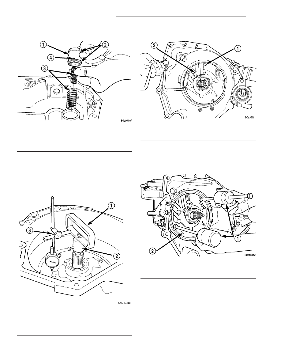
(14) Remove low/reverse accumulator (Fig. 28).

(15) Measure input shaft end play. Place transaxle

so input shaft is vertical. Set up end play set and
dial indicator as shown in (Fig. 29). Input shaft end
play should be within 0.13-0.64 mm (0.005-0.025
in.) 
If outside of this range, a #4 thrust plate change
is required. Record indicator reading for reference
upon reassembly.

(16) Remove oil pump-to-case bolts (Fig. 30).

CAUTION: Be sure input speed sensor is removed
before removing oil pump.

(17) Install pullers Tool C-3752 as shown in (Fig.

31).

Fig. 28 Remove Low/Reverse Accumulator

1 - ACCUMULATOR PISTON
2 - SEAL RINGS
3 - RETURN SPRINGS
4 - (NOTE NOTCH)

Fig. 29 Measure Input Shaft End Play Using End

Play Set 8266

1 - TOOL 8266–8
2 - TOOL 8266–2
3 - TOOL C-3339

Fig. 30 Remove Pump Attaching Bolts

1 - PUMP ATTACHING BOLTS
2 - PUMP HOUSING

Fig. 31 Install Tool C-3752

1 - PULLERS TOOL C-3752
2 - PUMP

21 - 130

41TE AUTOMATIC TRANSAXLE

RS

41TE AUTOMATIC TRANSAXLE (Continued)

(18) Remove oil pump assembly (Fig. 32) (Fig. 33).

(19) Remove oil pump gasket (Fig. 34).

CAUTION: If transaxle failure has occurred, the
cooler bypass valve must be replaced. Do not
re-use or attempt to clean valve.

(20) Remove cooler bypass valve (Fig. 35).

Fig. 32 Remove Oil Pump

1 - “PUSH IN” ON INPUT SHAFT WHILE REMOVING PUMP

Fig. 33 Oil Pump Removed

1 - OIL PUMP
2 - GASKET

Fig. 34 Remove Oil Pump Gasket

1 - PUMP GASKET

Fig. 35 Remove Bypass Valve

1 - COOLER BYPASS VALVE

RS

41TE AUTOMATIC TRANSAXLE

21 - 131

41TE AUTOMATIC TRANSAXLE (Continued)

(21) Remove #1 needle bearing (Fig. 36).

(22) Remove input clutch assembly (Fig. 37).

(23) Remove #4 thrust plate (Fig. 38).

(24) Remove front sun gear assembly and #4

thrust washer (Fig. 39).

Fig. 36 Remove Caged Needle Bearing

1 - #1 CAGED NEEDLE BEARING
2 - NOTE: TANGED SIDE OUT

Fig. 37 Remove Input Clutch Assembly

1 - INPUT CLUTCH ASSEMBLY
2 - #4 THRUST WASHER

Fig. 38 No. 4 Thrust Plate

1 - OVERDRIVE SHAFT ASSEMBLY
2 - #4 THRUST PLATE (SELECT)
3 - 3 DABS OF PETROLATUM FOR RETENTION

Fig. 39 Remove Front Sun Gear Assembly

1 - FRONT SUN GEAR ASSEMBLY
2 - #4 THRUST WASHER (FOUR TABS)

21 - 132

41TE AUTOMATIC TRANSAXLE

RS

41TE AUTOMATIC TRANSAXLE (Continued)

(25) Remove front carrier/rear annulus assembly

and #6 needle bearing (Fig. 40).

(26) Remove rear sun gear and #7 needle bearing

(Fig. 41).

NOTE: The number 7 needle bearing has three anti-
reversal tabs and is common with the number five
and number two position. The orientation should
allow the bearing to seat flat against the rear sun
gear (Fig. 42). A small amount of petrolatum can be
used to hold the bearing to the rear sun gear.

(27) Setup tool 5058 as shown in (Fig. 43). Com-

press 2/4 clutch return spring (just enough to remove
snap ring) and remove snap ring.

NOTE: Verify that Tool 5058 is centered properly
over the 2/4 clutch retainer before compressing. If
necessary, fasten the 5058 bar to the bellhousing
flange with any combination of locking pliers and
bolts to center the tool properly.

Fig. 40 Remove Front Carrier and Rear Annulus

Assembly

1 - #6 NEEDLE BEARING
2 - FRONT CARRIER AND REAR ANNULUS ASSEMBLY (TWIST
AND PULL OR PUSH TO REMOVE OR INSTALL).

Fig. 41 Remove Rear Sun Gear

1 - #7 NEEDLE BEARING
2 - REAR SUN GEAR

Fig. 42 Number 7 Bearing

1 - #7 NEEDLE BEARING
2 - REAR SUN GEAR

Fig. 43 Remove 2/4 Clutch Retainer Snap Ring

1 - TOOL 5058
2 - SCREWDRIVER
3 - SNAP RING
4 - 2/4 CLUTCH RETAINER

RS

41TE AUTOMATIC TRANSAXLE

21 - 133

41TE AUTOMATIC TRANSAXLE (Continued)


Content   ..  393  394  395  396   ..