Chrysler Town, Dodge Caravan. Manual - part 391


  Index      Chrysler     Chrysler TOWN & COUNTRY, VOYAGER, Dodge Caravan - service repair manual 2001-2007 year


Search            


Content   ..  389  390  391  392   ..


Chrysler Town, Dodge Caravan. Manual - part 391


SYNCHRONIZER

DESCRIPTION

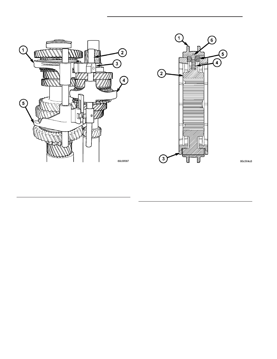
The T850 transaxle uses two styles of synchronizer

assemblies; a conventional single-cone style is used
for the 5th/Reverse and 3rd/4th applications (Fig.
277), and a dual-cone style for the 1st/2nd gear appli-
cation (Fig. 278).

DISASSEMBLY

Place synchronizer in a clean shop towel and wrap.

Press on inner hub. Carefully open up shop towel
and remove springs, balls, keys, hub, and sleeve.

CLEANING

CLEAN

Do not attempt to clean the blocking rings in sol-

vent. The friction material will become contaminated.
Place synchronizer components in a suitable holder
and clean with solvent. Air dry.

INSPECTION

INSPECT

Proper inspection of components involve:
• Teeth, for wear, scuffed, nicked, burred, or broken

teeth

• Keys, for wear or distortion

• Balls and springs, for distortion, cracks, or wear
If any of these conditions exist in these compo-

nents, replace as necessary.

ASSEMBLY

(1) Position synchronizer hub onto work bench.

Hub is non-directional.

(2) Install springs into hub slot.
(3) Insert key into hub and spring.
(4) Apply petroleum jelly to the hole in the key.

Insert balls into each key.

(5) Slide sleeve over the hub and depress balls as

you carefully slip the sleeve into position.

Fig. 276 Shift Fork/Shaft Components

1 - 5/R FORK
2 - SHAFT/LINK ASSEMBLY
3 - LINK
4 - 3/4 FORK
5 - 1/2 FORK

Fig. 277 3/4-5/R Synchronizer Assembly

1 - SLEEVE
2 - HUB
3 - BLOCKER RING (2)
4 - SPRING (3)
5 - KEY (3)
6 - BALL (3)

21 - 114

T850 MANUAL TRANSAXLE

RS

SHIFT FORK AND SHAFT (Continued)

VEHICLE SPEED SENSOR

REMOVAL

(1) Raise vehicle on hoist.
(2) Disconnect the speed sensor connector (Fig. 279).

CAUTION: Clean area around speed sensor before
removing to prevent dirt from entering the transaxle
during speed sensor removal.

(3) Remove speed sensor retaining bolt (Fig. 279).
(4) Remove speed sensor from transaxle.

CAUTION: Carefully remove vehicle speed sensor
so that sensor drive gear does not fall into trans-
axle. Should sensor drive gear fall into the trans-
axle during sensor removal, drive gear must be
reattached to sensor.

(5) Remove speed sensor drive gear from speed

sensor.

INSTALLATION

(1) Install pinion gear to speed sensor (Fig. 279).
(2) Using a NEW o-ring, install the speed sensor

to the transaxle (Fig. 279).

(3) Install the bolt and torque to 7 N·m (60 in.

lbs.).

(4) Connect speed sensor connector (Fig. 279).
(5) Lower vehicle and road test to verify proper

speedometer operation.

Fig. 278 1/2 Synchronizer Assembly

1 - SLEEVE
2 - REACTOR RING (2)
3 - HUB
4 - BLOCKER RING (2)
5 - SLEEVE
6 - FRICTION CONE (2)
7 - SPRING (3)
8 - KEY (3)
9 - BALL (3)

Fig. 279 Speed Sensor and Pinion Removal/

Installation—Typical

1 - CONNECTOR
2 - SENSOR
3 - O-RING
4 - GEAR

RS

T850 MANUAL TRANSAXLE

21 - 115

SYNCHRONIZER (Continued)

41TE AUTOMATIC TRANSAXLE

TABLE OF CONTENTS

page

page

41TE AUTOMATIC TRANSAXLE

DESCRIPTION

. . . . . . . . . . . . . . . . . . . . . . . . 117

OPERATION

. . . . . . . . . . . . . . . . . . . . . . . . . . 119

DIAGNOSIS AND TESTING

DIAGNOSIS AND TESTING - 41TE

TRANSAXLE GENERAL DIAGNOSIS . . . . . . 119

DIAGNOSIS AND TESTING - ROAD TEST

. . 119

DIAGNOSIS AND TESTING - HYDRAULIC

PRESSURE TESTS . . . . . . . . . . . . . . . . . . . 120

DIAGNOSIS AND TESTING - CLUTCH AIR

PRESSURE TESTS . . . . . . . . . . . . . . . . . . . 122

DIAGNOSIS AND TESTING - TORQUE

CONVERTER HOUSING FLUID LEAKAGE . . 123

REMOVAL

. . . . . . . . . . . . . . . . . . . . . . . . . . . . 124

DISASSEMBLY

. . . . . . . . . . . . . . . . . . . . . . . . 125

ASSEMBLY

. . . . . . . . . . . . . . . . . . . . . . . . . . . 144

INSTALLATION

. . . . . . . . . . . . . . . . . . . . . . . . 166

SCHEMATICS AND DIAGRAMS

41TE TRANSAXLE HYDRAULIC

SCHEMATICS . . . . . . . . . . . . . . . . . . . . . . . 169

SPECIFICATIONS - 41TE TRANSAXLE

. . . . . . 181

SPECIAL TOOLS

41TE AUTOMATIC TRANSAXLE

. . . . . . . . . 183

ACCUMULATOR

DESCRIPTION

. . . . . . . . . . . . . . . . . . . . . . . . 188

OPERATION

. . . . . . . . . . . . . . . . . . . . . . . . . . 189

AUTOSTICK SWITCH

DESCRIPTION

. . . . . . . . . . . . . . . . . . . . . . . . 189

OPERATION

. . . . . . . . . . . . . . . . . . . . . . . . . . 189

DRIVING CLUTCHES

DESCRIPTION

. . . . . . . . . . . . . . . . . . . . . . . . 190

OPERATION

. . . . . . . . . . . . . . . . . . . . . . . . . . 190

FINAL DRIVE

DISASSEMBLY

. . . . . . . . . . . . . . . . . . . . . . . . 190

ASSEMBLY

. . . . . . . . . . . . . . . . . . . . . . . . . . . 195

ADJUSTMENTS

ADJUSTMENT - DIFFERENTIAL BEARING

PRELOAD . . . . . . . . . . . . . . . . . . . . . . . . . . 199

FLUID

STANDARD PROCEDURE

FLUID LEVEL AND CONDITION CHECK

. . . 201

STANDARD PROCEDURE - FLUID AND

FILTER SERVICE . . . . . . . . . . . . . . . . . . . . . 203

GEAR SHIFT CABLE

REMOVAL

. . . . . . . . . . . . . . . . . . . . . . . . . . . . 204

INSTALLATION

. . . . . . . . . . . . . . . . . . . . . . . . 205

ADJUSTMENTS

GEARSHIFT CABLE ADJUSTMENT

. . . . . . . 206

HOLDING CLUTCHES

DESCRIPTION

. . . . . . . . . . . . . . . . . . . . . . . . 207

OPERATION

. . . . . . . . . . . . . . . . . . . . . . . . . . 207

INPUT CLUTCH ASSEMBLY

DISASSEMBLY

. . . . . . . . . . . . . . . . . . . . . . . . 208

ASSEMBLY

. . . . . . . . . . . . . . . . . . . . . . . . . . . 216

OIL PUMP

DESCRIPTION

. . . . . . . . . . . . . . . . . . . . . . . . 230

OPERATION

. . . . . . . . . . . . . . . . . . . . . . . . . . 230

DISASSEMBLY

. . . . . . . . . . . . . . . . . . . . . . . . 230

ASSEMBLY

. . . . . . . . . . . . . . . . . . . . . . . . . . . 232

PLANETARY GEARTRAIN

DESCRIPTION

. . . . . . . . . . . . . . . . . . . . . . . . 232

OPERATION

. . . . . . . . . . . . . . . . . . . . . . . . . . 232

SEAL - OIL PUMP

REMOVAL

. . . . . . . . . . . . . . . . . . . . . . . . . . . . 232

INSTALLATION

. . . . . . . . . . . . . . . . . . . . . . . . 233

SHIFT INTERLOCK SOLENOID

DESCRIPTION

. . . . . . . . . . . . . . . . . . . . . . . . 233

OPERATION

. . . . . . . . . . . . . . . . . . . . . . . . . . 233

DIAGNOSIS AND TESTING - BRAKE/

TRANSMISSION SHIFT INTERLOCK
SOLENOID

. . . . . . . . . . . . . . . . . . . . . . . . . . 235

REMOVAL

. . . . . . . . . . . . . . . . . . . . . . . . . . . . 235

INSTALLATION

. . . . . . . . . . . . . . . . . . . . . . . . 236

SOLENOID/PRESSURE SWITCH ASSY

DESCRIPTION

. . . . . . . . . . . . . . . . . . . . . . . . 237

OPERATION

. . . . . . . . . . . . . . . . . . . . . . . . . . 237

REMOVAL

. . . . . . . . . . . . . . . . . . . . . . . . . . . . 238

INSTALLATION

. . . . . . . . . . . . . . . . . . . . . . . . 239

SPEED SENSOR - INPUT

DESCRIPTION

. . . . . . . . . . . . . . . . . . . . . . . . 239

OPERATION

. . . . . . . . . . . . . . . . . . . . . . . . . . 240

REMOVAL

. . . . . . . . . . . . . . . . . . . . . . . . . . . . 240

INSTALLATION

. . . . . . . . . . . . . . . . . . . . . . . . 240

SPEED SENSOR - OUTPUT

DESCRIPTION

. . . . . . . . . . . . . . . . . . . . . . . . 241

OPERATION

. . . . . . . . . . . . . . . . . . . . . . . . . . 241

REMOVAL

. . . . . . . . . . . . . . . . . . . . . . . . . . . . 241

INSTALLATION

. . . . . . . . . . . . . . . . . . . . . . . . 242

TORQUE CONVERTER

DESCRIPTION

. . . . . . . . . . . . . . . . . . . . . . . . 242

OPERATION

. . . . . . . . . . . . . . . . . . . . . . . . . . 245

REMOVAL

. . . . . . . . . . . . . . . . . . . . . . . . . . . . 247

INSTALLATION

. . . . . . . . . . . . . . . . . . . . . . . . 247

TRANSMISSION CONTROL RELAY

DESCRIPTION

. . . . . . . . . . . . . . . . . . . . . . . . 247

OPERATION

. . . . . . . . . . . . . . . . . . . . . . . . . . 248

21 - 116

41TE AUTOMATIC TRANSAXLE

RS

TRANSMISSION RANGE SENSOR

DESCRIPTION

. . . . . . . . . . . . . . . . . . . . . . . . 248

OPERATION

. . . . . . . . . . . . . . . . . . . . . . . . . . 248

REMOVAL

. . . . . . . . . . . . . . . . . . . . . . . . . . . . 249

INSTALLATION

. . . . . . . . . . . . . . . . . . . . . . . . 249

TRD LINK

DESCRIPTION

. . . . . . . . . . . . . . . . . . . . . . . . 249

OPERATION

. . . . . . . . . . . . . . . . . . . . . . . . . . 249

VALVE BODY

DESCRIPTION

. . . . . . . . . . . . . . . . . . . . . . . . 250

OPERATION

. . . . . . . . . . . . . . . . . . . . . . . . . . 250

REMOVAL

. . . . . . . . . . . . . . . . . . . . . . . . . . . . 251

DISASSEMBLY

. . . . . . . . . . . . . . . . . . . . . . . . 252

ASSEMBLY

. . . . . . . . . . . . . . . . . . . . . . . . . . . 257

INSTALLATION

. . . . . . . . . . . . . . . . . . . . . . . . 262

41TE AUTOMATIC
TRANSAXLE

DESCRIPTION

The 41TE (Fig. 1) is a four-speed transaxle that is

a conventional hydraulic/mechanical assembly with
an integral differential, and is controlled with adap-
tive electronic controls and monitors. The hydraulic
system of the transaxle consists of the transaxle
fluid, fluid passages, hydraulic valves, and various
line pressure control components. An input clutch
assembly which houses the underdrive, overdrive,
and reverse clutches is used. It also utilizes separate
holding clutches: 2nd/4th gear and Low/Reverse. The
primary mechanical components of the transaxle con-
sist of the following:

• Three multiple disc input clutches

• Two multiple disc holding clutches

• Four hydraulic accumulators

• Two planetary gear sets

• Hydraulic oil pump

• Valve body

• Solenoid/Pressure switch assembly

• Integral differential assembly

Control of the transaxle is accomplished by fully

adaptive electronics. Optimum shift scheduling is
accomplished through continuous real-time sensor
feedback information provided to the Powertrain
Control Module (PCM) or Transmission Control Mod-
ule (TCM).

The PCM/TCM is the heart of the electronic control

system and relies on information from various direct
and indirect inputs (sensors, switches, etc.) to deter-
mine driver demand and vehicle operating condi-
tions. With this information, the PCM/TCM can
calculate and perform timely and quality shifts
through various output or control devices (solenoid
pack, transmission control relay, etc.).

The PCM/TCM also performs certain self-diagnos-

tic functions and provides comprehensive information
(sensor data, DTC’s, etc.) which is helpful in proper
diagnosis and repair. This information can be viewed
with the DRB scan tool.

RS

41TE AUTOMATIC TRANSAXLE

21 - 117


Content   ..  389  390  391  392   ..