Chrysler Town, Dodge Caravan. Manual - part 365


  Index      Chrysler     Chrysler TOWN & COUNTRY, VOYAGER, Dodge Caravan - service repair manual 2001-2007 year


Search            


Content   ..  363  364  365  366   ..


Chrysler Town, Dodge Caravan. Manual - part 365


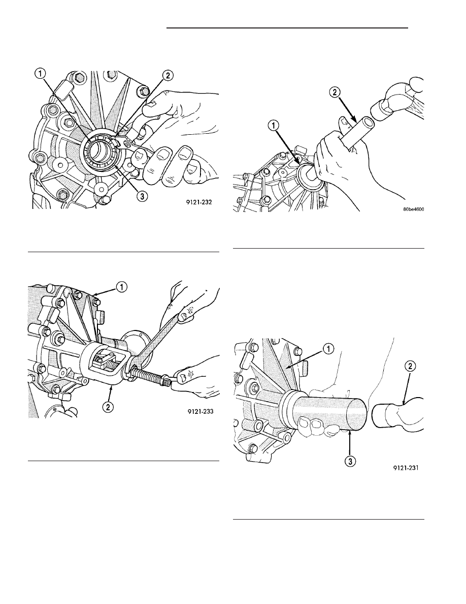
(4) Remove bearing retaining snap ring (Fig. 18).

(5) Use bearing puller MD998346 to remove bear-

ing (Fig. 19).

INSTALLATION

The end cover ball bearing can be removed and

installed without removing the Power Transfer Unit
from the vehicle. When replacing the bearing the out-
put seal must be removed to gain access to the bear-
ing.

CAUTION: When installing bearing, position the
bearing in place by hand square to the bore. Other-
wise, bearing and/or housing damage may occur
upon installation.

(1) Use installer MD998200 and driver handle

C-4171 to install bearing (Fig. 20) into the housing.

(2) Install bearing retaining snap ring.

CAUTION: When installing bearing retaining snap
ring, be sure to index the snap ring so that the
snap ring does not cover bearing oil passage.

(3) Install

new

outer

half

shaft

seal

using

MD998334 seal installer (Fig. 21). Do not reuse the
old seal.

(4) Reinstall right front half shaft.
(5) Check and fill fluids as required.

Fig. 18 Bearing Snap Ring

1 - BEARING
2 - SNAP RING PLIERS
3 - BEARING SNAP RING

Fig. 19 Bearing Removal

1 - P.T.U. END COVER
2 - SPECIAL TOOL
MD998346

Fig. 20 Bearing Installation

1 - SPECIAL TOOL MD998200
2 - SPECIAL C-4171

Fig. 21 Installing New Seal

1 - P.T.U. END COVER
2 - HAMMER
3 - SPECIAL TOOL
MD998334

21 - 10

POWER TRANSFER UNIT

RS

END COVER BALL BEARING (Continued)

END COVER SEAL

REMOVAL

The Power Transfer Unit must be removed from

the vehicle to perform this operation. (Refer to 21 -
TRANSMISSION/TRANSAXLE/POWER TRANSFER
UNIT - REMOVAL)

(1) Remove P.T.U. end cover bolts (Fig. 22).

(2) Gently tap on end cover ears with a hammer to

separate end cover from the case (Fig. 23).

(3) Clean and inspect sealer surfaces.

INSTALLATION

(1) Reinstall cover and tighten bolts to 28 N·m

(250 in. lbs.) in the sequence shown in (Fig. 24).
Retighten first bolt after all others are tight.

CAUTION: When end cover is installed be careful
not to damage the P.T.U. Input Shaft Cover Seal.

(2) Reinstall P.T.U. into vehicle.
(3) Check and fill fluids as required.

Fig. 22 P.T.U. End Cover Bolts

1 - POWER TRANSFER UNIT
2 - FILL PLUG
3 - END COVER
4 - OUTPUT SHAFT

Fig. 23 End Cover Removal

1 - END COVER EARS
2 - HAMMER
3 - POWER TRANSFER UNIT

Fig. 24 Bolt Tightening Sequence

RS

POWER TRANSFER UNIT

21 - 11

HALF SHAFT INNER SEAL

REMOVAL

The power transfer unit half shaft inner seal is the

smaller of the two seals located on the inside of the
end cover.

(1) Remove power transfer unit from the vehicle.
(2) Remove end cover bolts (Fig. 25).

(3) Tap on end cover ears to separate cover from

case (Fig. 26).

(4) Drive seal out with a hammer and small chisel

(Fig. 27).

INSTALLATION

The power transfer unit half shaft inner seal is the

smaller of the two seals located on the inside of the
end cover.

(1) Clean and inspect seal area.
(2) Install seal with a 1 1/16 inch socket (Fig. 28).

The seal must be installed with the spring side of the
seal facing end cover ball bearing. The seal will bot-
tom against a machined shoulder in the cover.

(3) Clean sealing surfaces of the end cover and

P.T.U. case. Apply a bead of Mopar

t Gasket Maker,

Loctite Gasket Eliminator No. 518 or equivalent.

Fig. 26 End Cover Removal

1 - END COVER EARS
2 - HAMMER
3 - POWER TRANSFER UNIT

Fig. 27 Seal Removal

1 - END COVER
2 - END COVER SEAL
3 - AXLE SHAFT SEAL

Fig. 25 End Cover Bolts

1 - POWER TRANSFER UNIT
2 - FILL PLUG
3 - END COVER
4 - OUTPUT SHAFT

21 - 12

POWER TRANSFER UNIT

RS

(4) Place end cover onto P.T.U. case and install

bolts. Tighten bolts to 28 N·m (250 in. lbs.) in the
sequence shown in (Fig. 29). Retighten first bolt after
all other bolts are tight.

(5) Reinstall P.T.U. assembly.
(6) Check and fill fluids as required.

INPUT SHAFT COVER SEAL

REMOVAL

The power transfer unit input shaft cover seal is

the larger of the two seals located on the inside of
the end cover. The differential bearing cup must be
removed to service this seal.

(1) Remove P.T.U. end cover bolts (Fig. 30).

(2) Gently tap on end cover ears to separate cover

from case (Fig. 31).

(3) Use special tool No. 6514 and remove the dif-

ferential bearing race located in the end cover (Fig.
32). The race must be removed to gain access to the
seal.2

(4) Use special tool No. 7794-A to remove seal (Fig.

33).

Fig. 28 Seal Installation

1 - END COVER
2 - SOCKET
3 - HAMMER

Fig. 29 Bolt Tightening Sequence

Fig. 30 P.T.U. End Cover Bolts

1 - POWER TRANSFER UNIT
2 - FILL PLUG
3 - END COVER
4 - OUTPUT SHAFT

RS

POWER TRANSFER UNIT

21 - 13

HALF SHAFT INNER SEAL (Continued)


Content   ..  363  364  365  366   ..