Chrysler Town, Dodge Caravan. Manual - part 125


  Index      Chrysler     Chrysler TOWN & COUNTRY, VOYAGER, Dodge Caravan - service repair manual 2001-2007 year


Search            


Content   ..  123  124  125  126   ..


Chrysler Town, Dodge Caravan. Manual - part 125


REMOVAL

(1) Disconnect and isolate the battery negative

cable.

(2) Remove door trim panel. Refer to Body, Door -

Front, Trim Panel, Removal.

(3) Disconnect wire connector from back of door

lock switch.

(4) Remove two screws to door lock switch.
(5) Remove switch from vehicle.

INSTALLATION

(1) Install the switch into the vehicle.
(2) Install the two screws to door lock switch.
(3) Connect wire connector to back of door lock

switch.

(4) Install door trim panel. Refer to Body, Door -

Front, Trim Panel, Installation.

(5) Connect the battery negative cable.

KEYLESS ENTRY
TRANSMITTER

DIAGNOSIS AND TESTING - KEYLESS ENTRY
TRANSMITTER

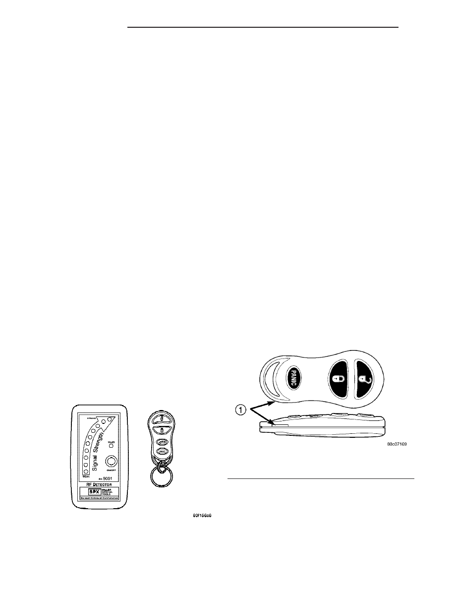
Using special tool 9001, first test to ensure that

the transmitter is functioning. Typical testing dis-
tance is 2.5 centimeters (1 inch) for Asian transmit-
ters and 30.5 centimeters (12 inches) for all others.
To test, position the transmitter as shown (Fig. 3).
Press any transmitter button, then test each button
individually. The tool will beep if a radio signal
strength that lights five or more LED’s is detected.
Repeat this test three times. If transmitter fails any
of the test, test the batteries. If batteries test OK,
refer to the Diagnostic Procedures manual.

STANDARD PROCEDURE

STANDARD PROCEDURE - HORN CHIRP
PREFERENCE

DISABLING

The horn chirp can be toggled using a DRB III

t or

by using a programmed Remote Keyless Entry (RKE)
transmitter.

To DISABLE (cancelling) the horn chirp feature,

press and hold the transmitter LOCK button for a
minimum of five seconds. While pressing the LOCK
button in, press the UNLOCK button. The horn chirp
feature will not function until the above procedure is
repeated.

ENABLING

The horn chirp can be toggled using a DRB III

t or

by using the Remote Keyless Entry (RKE) transmit-
ter.

To ENABLE (reinstate) the horn chirp feature, use

any one of the four programmed key fob transmitters
and reverse the above procedures. It will ENABLE
the horn chirp feature for all transmitters.

STANDARD PROCEDURE - BATTERY
REPLACEMENT

(1) With the transmitter buttons facing down, use

a coin (a penny is suggested) to pry the two halves of
the transmitter apart (Fig. 4). Make sure not to dam-
age the rubber gasket during separation of the hous-
ing halves.

(2) Remove the battery from the transmitter back

housing holder.

(3) Replace the batteries. Avoid touching the new

batteries with your fingers, Skin oils may cause bat-
tery deterioration. If you touch a battery, clean it off
with rubbing alcohol.

(4) To assemble the transmitter case, snap the two

halves together.

Fig. 3 TRANSMITTER DIAGNOSIS

Fig. 4 RKE TRANSMITTER BATTERY

REPLACEMENT - TYPICAL

1 - INSERT THIN COIN

8N - 42

POWER LOCKS

RS

DOOR LOCK SWITCH (Continued)

STANDARD PROCEDURE - RKE TRANSMITTER
PROGRAMING

(1) Using a functional key fob transmitter, unlock

the vehicle and disarm the Vehicle Theft Security
System.

(2) Insert ignition key into the ignition switch.
(3) Turn the ignition switch to RUN position with-

out starting engine.

(4) Using a functional key fob transmitter, press

and hold the UNLOCK button for a minimum five
seconds (maximum ten seconds).

(5) While

still

holding

UNLOCK

button,

and

before ten seconds passes, press the PANIC button
and release both at the same time. A single chime
will sound to indicate that the transmitter program-
ming mode has been entered (allow 3 seconds for
chime to sound).

(6) Within 30 seconds of the chime, press and

release the “LOCK” and “UNLOCK” buttons on the
transmitter at the same time. Then press and release
any button on the same transmitter and a chime will
sound after successfully programming the transmit-
ter.

(7) Repeat steps 5 and 6 for all transmitters that

will be used with this vehicle (up to 4 total).

(8) Turn ignition to the OFF position. Transmitter

programming mode will discontinue after 60 seconds.
All transmitter programming must be com-
pleted within time specified.

SPECIFICATIONS

RANGE

Normal operation range is up to a distance of 7

meters (23 ft.) of the vehicle. Range may be better or
worse depending on the environment around the
vehicle. Closeness to a radio frequency transmitter
such as a radio station tower that is broadcasting on
105 MHz FM or a 156 MHz 2–way communication
station, may degrade operational range, while range
in an open field will be enhanced.

BATTERY

The batteries can be removed without special tools

and are readily available at local retail stores. The

recommended battery is Duracell DL 2016 or equiva-
lent, TWO cells are required. Battery life is about
three years minimum.

CAUTION: Do not touch the battery terminals or
handle the batteries any more than necessary.
Hands must be clean and dry.

REMOTE KEYLESS ENTRY
MODULE

DESCRIPTION

The RKE module is capable of retaining up to four

different Vehicle Access Codes.

OPERATION

Whenever the vehicle battery power is interrupted

the RKE Module will retain all vehicle access codes
in its memory. When replacing or adding a key fob
transmitter (maximum 4) a DRB III

t scan tool is

required to program the RKE Module to accept the
new Vehicle Access Code if a customer owned trans-
mitter is not available. Refer to Electrical, Remote
Keyless Entry Module, Standard Procedure - Pro-
gramming RKE Module or the Proper Body Diagnos-
tic Procedures manual.

DIAGNOSIS AND TESTING - REMOTE KEYLESS
ENTRY MODULE

Refer to the appropriate wiring information. The

wiring information includes wiring diagrams, proper
wire and connector repair procedures, further details
on wire harness routing and retention, as well as
pin-out and location views for the various wire har-
ness connectors, splices and grounds. Refer to the
proper Body Diagnostic Procedures Manual for test-
ing the Remote Keyless Entry system using a
DRB III

t scan tool. Also refer to other interrelated

systems groups within this manual:

• Vehicle Theft Security System

• Power Seats

• Power Mirrors

RS

POWER LOCKS

8N - 43

KEYLESS ENTRY TRANSMITTER (Continued)

REMOVAL

(1) Disconnect and isolate the battery negative

cable.

(2) Remove instrument panel top cover (Refer to

23 - BODY/INSTRUMENT PANEL/INSTRUMENT
PANEL TOP PAD - REMOVAL).

(3) Remove screws holding RKE module to instru-

ment panel.

(4) Disconnect wire connector from RKE module

(Fig. 5).

(5) Remove the RKE module from vehicle.

INSTALLATION

(1) Position the RKE module and install the

screws.

(2) Connect the wire connector to the RKE module

(Fig. 5).

(3) Install the instrument panel top pad.
(4) Connect the battery negative cable.

SLIDING DOOR LOCK MOTOR

REMOVAL

(1) Disconnect and isolate the negative battery

cable.

(2) Remove sliding door trim panel (Refer to 23 -

BODY/DOORS - SLIDING/TRIM PANEL - REMOV-
AL).

(3) Remove sound pad as necessary.
(4) Remove latch/lock control cover.
(5) Remove latch/lock control.
(6) Remove screws holding door lock motor to

latch/lock control (Fig. 6).

(7) Remove lock motor from control.

INSTALLATION

(1) Position the lock motor on the latch/lock.
(2) Install the screws retaining the motor to the

latch/lock.

(3) Install the latch/lock control.
(4) Install the latch/lock control cover.
(5) Install the sound pad and trim panel to the

sliding door.

Fig. 5 RKE MODULE

1 - REMOTE KEYLESS ENTRY MODULE
2 - INSTRUMENT PANEL
3 - DEMISTER DUCT

Fig. 6 SLIDING DOOR LOCK MOTOR

1 - SLIDING DOOR POWER LOCK MOTOR
2 - LATCH/LOCK CONTROL

8N - 44

POWER LOCKS

RS

REMOTE KEYLESS ENTRY MODULE (Continued)

POWER MIRRORS

TABLE OF CONTENTS

page

page

POWER MIRRORS

DESCRIPTION

. . . . . . . . . . . . . . . . . . . . . . . . . 45

OPERATION

. . . . . . . . . . . . . . . . . . . . . . . . . . . 45

DIAGNOSIS AND TESTING - POWER

MIRRORS

. . . . . . . . . . . . . . . . . . . . . . . . . . . 46

AUTOMATIC DAY / NIGHT MIRROR

DESCRIPTION

. . . . . . . . . . . . . . . . . . . . . . . . . 47

OPERATION

. . . . . . . . . . . . . . . . . . . . . . . . . . . 47

DIAGNOSIS AND TESTING - AUTOMATIC DAY

/ NIGHT MIRROR

. . . . . . . . . . . . . . . . . . . . . . 47

POWER FOLDAWAY MIRROR SWITCH -

EXPORT
DESCRIPTION

. . . . . . . . . . . . . . . . . . . . . . . . . 48

OPERATION

. . . . . . . . . . . . . . . . . . . . . . . . . . . 48

REMOVAL

. . . . . . . . . . . . . . . . . . . . . . . . . . . . . 48

INSTALLATION

. . . . . . . . . . . . . . . . . . . . . . . . . 49

REMOTE SWITCH

DIAGNOSIS AND TESTING - REMOTE

SWITCH

. . . . . . . . . . . . . . . . . . . . . . . . . . . . 49

REMOVAL

. . . . . . . . . . . . . . . . . . . . . . . . . . . . . 49

INSTALLATION

. . . . . . . . . . . . . . . . . . . . . . . . . 49

SIDEVIEW MIRROR

REMOVAL

. . . . . . . . . . . . . . . . . . . . . . . . . . . . . 49

POWER MIRRORS

DESCRIPTION

If equipped with power mirrors, the control switch

is located on the instrument panel to the left of the
headlamp switch.

OPERATION

The power mirrors are connected to battery feed at

all times. Each mirror head contains two electric
motors, two drive mechanisms, an electric heating
element, and the mirror glass. If the vehicle is
equipped with the optional memory system, the
driver side mirror head also contains both a horizon-
tal and a vertical motor position sensor. One motor
and drive controls mirror up-and-down movement,
and the other controls right-and-left movement.

An optional driver side outside electrochromic mir-

ror is able to automatically change its reflectance
level. This mirror is controlled by the circuitry of the
automatic day/night inside rear view mirror. A thin
layer of electrochromic material between two pieces
of conductive glass make up the face of the mirror.
Two photocell sensors on the inside rear view mirror
are used to monitor light levels and adjust the reflec-
tance of both the inside and driver side outside mir-
rors. This change in reflectance helps to reduce the
glare of headlamps approaching the vehicle from the
rear. (Refer to 8 - ELECTRICAL/POWER MIRRORS/
AUTOMATIC DAY / NIGHT MIRROR - DESCRIP-
TION) for more information on this system.

The motors which operate the mirrors are part of

the mirror assembly and cannot be serviced sepa-
rately.

RS

POWER MIRRORS

8N - 45


Content   ..  123  124  125  126   ..