Chrysler Sebring, Stratus sedan, Sebring Convertible. Manual - part 346


  Index      Chrysler     Chrysler Sebring, Stratus sedan, Sebring Convertible - service repair manual 2001-2007 year


Search            


Content   ..  344  345  346  347   ..


Chrysler Sebring, Stratus sedan, Sebring Convertible. Manual - part 346


REMOVAL

(1) Disconnect and isolate the battery negative

cable.

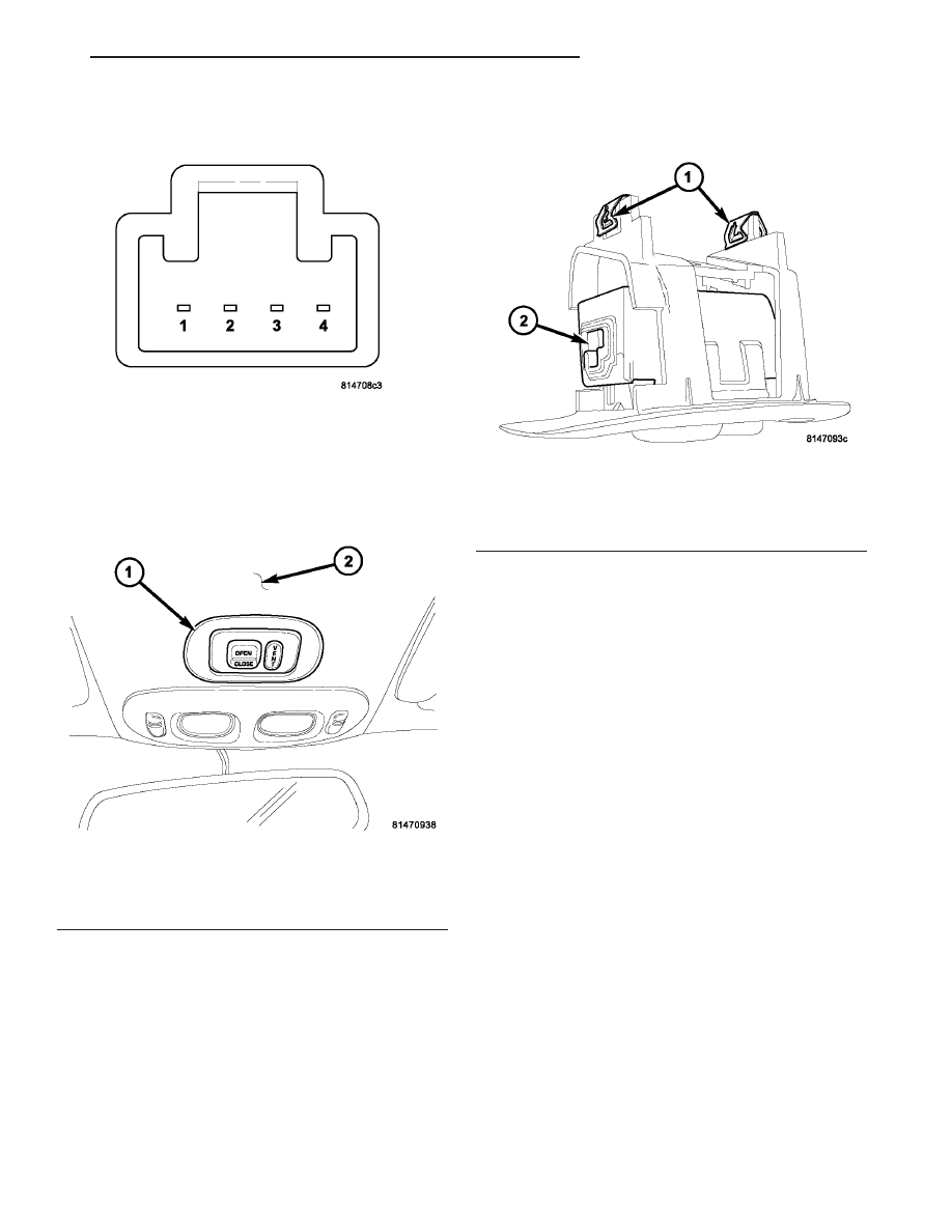
(2) Using a suitable flat bladed tool separate the

sunroof switch from the headliner, by carefully pull-
ing down on the sides of the switch bezel, to release
the retaining clips (Fig. 3).

(3) Disconnect the switch electrical connector and

remove the switch from the vehicle.

INSTALLATION

(1) Position the sunroof switch in the vehicle.
(2) Connect the switch electrical connector to the

connector receptacle, (Fig. 4).

(3) Position the sunroof switch against the head-

liner and push the switch to properly seat the retain-
ing clips (Fig. 4).

(4) Connect the battery negative cable.
(5) Confirm proper sunroof system operation.

Fig. 2 SUNROOF SWITCH PINOUT

Fig. 3 SUNROOF SWITCH LOCATION

1 - POWER SUNROOF SWITCH BEZEL
2 - HEADLINER

Fig. 4 SUNROOF SWITCH RETAINING CLIPS

1 - RETAINING CLIPS
2 - ELECTRICAL CONNECTOR RECEPTACLE

JR

POWER TOP - SUNROOF

8N - 27

SWITCH - SUNROOF (Continued)

POWER WINDOWS

TABLE OF CONTENTS

page

page

POWER WINDOWS

DESCRIPTION

. . . . . . . . . . . . . . . . . . . . . . . . . 28

OPERATION

. . . . . . . . . . . . . . . . . . . . . . . . . . . 28

DIAGNOSIS AND TESTING - POWER

WINDOWS

. . . . . . . . . . . . . . . . . . . . . . . . . . . 28

WINDOW DROP RELAY

REMOVAL

. . . . . . . . . . . . . . . . . . . . . . . . . . . . . 29

INSTALLATION

. . . . . . . . . . . . . . . . . . . . . . . . . 29

WINDOW MOTOR

DIAGNOSIS AND TESTING - WINDOW

MOTOR

. . . . . . . . . . . . . . . . . . . . . . . . . . . . . 29

REMOVAL

. . . . . . . . . . . . . . . . . . . . . . . . . . . . . 29

INSTALLATION

. . . . . . . . . . . . . . . . . . . . . . . . . 29

WINDOW SWITCH

DIAGNOSIS AND TESTING - WINDOW

SWITCH

. . . . . . . . . . . . . . . . . . . . . . . . . . . . 29

REMOVAL

. . . . . . . . . . . . . . . . . . . . . . . . . . . . . 30

INSTALLATION

. . . . . . . . . . . . . . . . . . . . . . . . . 30

POWER WINDOWS

DESCRIPTION

The power window system allows each of the door

windows to be raised and lowered electrically by
actuating a switch on the trim panel of each respec-
tive door. A master switch on the driver side front
door trim panel allows the driver to raise or lower
each of the passenger door windows, and to lock out
the individual switches on the passenger doors from
operation. The power window system receives battery
feed through a 30 amp circuit breaker in the junction
block, only when the ignition switch is in the RUN
position.

The power top switch (JR27 only) has three dis-

tinct functions:

• Top Down - This is the first detent on the down

side of the switch. Holding the switch in this position
will lower the top only.

• Top Down/4 window down - This is the sec-

ond detent on the switch. Holding the switch in this
position lowers the convertible top and all 4 windows
down simultaneously only if held in this position.

• Top Up - Holding the switch in this position

raises the convertible top to the closed position. It
will also lower all 4 windows approximately 3 inches
to prevent seal damage.

The power window system includes the power win-

dow switches on each door trim panel, the circuit
breaker in the junction block, and the power window
motors inside each door. For service of mechanical
components, such as the regulator, lift plate, window
tracks, or glass refer to Group 23 - Body.

OPERATION

Front and rear door window lift motors are of the

permanent magnet type. A battery positive and neg-
ative connection to either of the two motor terminals
will cause the motor to rotate in one direction.
Reversing current through these same two connec-
tions will cause the motor to rotate in the opposite
direction.

Each individual motor is grounded through the

master switch.

DIAGNOSIS AND TESTING - POWER
WINDOWS

CIRCUIT TEST

The following circuit test sequence determines

whether or not voltage is continuous through the
body harness to switch.

(1) Remove the driver door trim panel.
(2) Carefully separate wiring harness connector

from switch body.

(3) Using a voltmeter, connect the ground lead to

the Pin 10 of the wiring harness connector.

(4) Using the positive lead, check Pin 1 of the har-

ness connector for battery voltage. If OK, refer to
Window Switch Test. If not OK, check 30 amp circuit
breaker in the Junction Block. If the circuit breaker
is OK, repair wire as necessary. For wiring, specific
connector type and location, refer to the appropriate
wiring information. The wiring information includes
wiring diagrams, proper wire and connector repair
procedures, details of wire harness routing and
retention, connector pin-out information and location
views for the various wire harness connectors, splices
and grounds.

8N - 28

POWER WINDOWS

JR

WINDOW DROP RELAY TEST - JR27 ONLY

The following test should be performed if all win-

dows do not lower when the top switch is in the
down position.

(1)

Check for battery voltage at pins C1, F1 and D1 of
the window drop relay wire connector. If OK, go to
Step 2. If not OK, check the circuit breaker and fuse
or check for a shorted or open wire. Repair as neces-
sary.

(2) Check pin D1 of the window drop relay wire

connector for ground while pressing the top down
switch. If not OK, check the power top up/down relay
wiring. If OK, replace the window drop relay.

WINDOW DROP RELAY

REMOVAL

(1) Disconnect and isolate the battery negative

cable.

(2) Remove door trim panel.
(3) Peel back the waterdam to expose the window

drop relay.

(4) Disconnect the wire harness connector.
(5) Remove the window drop relay from the door

panel.

INSTALLATION

(1) Install the window drop relay to the door

panel.

(2) Connect the wire harness connector.
(3) Place the waterdam into position on the door

panel,

(4) Install door trim panel.
(5) Connect the battery negative cable.

WINDOW MOTOR

DIAGNOSIS AND TESTING - WINDOW MOTOR

(1) Remove door trim panel. (Refer to 23 - BODY/

DOOR - FRONT/TRIM PANEL - REMOVAL).

(2) Connect positive (+) lead from a test battery to

either of the two motor terminals.

(3) Connect negative (-) lead from test battery to

remaining motor terminal.

(4) The motor should now rotate in one direction to

either move window up or down.

(a) If window happens to already be in full UP

position and motor is connected so as to move it in
UP direction no movement will be observed.

(b) Likewise, motor connected to move window

in DOWN direction no movement will be observed
if window is already in full DOWN position.

(c)

Reverse battery leads in Step 1 and Step 2

and window should now move. If window does not
move, replace motor.
(5) If window moved completely up or down, the

test leads should be reversed one more time to com-
plete a full window travel inspection.

(6) If window does not move, check to make sure

that it is free.

(7) It is necessary that the window be free to slide

up and down in the glass channels. If the window is
not free to move up and down, the window lift motor
will not be able to move the glass.

(8) To determine if the glass is free, disconnect the

regulator from the glass lift plate. Remove the two
attaching screws, and slide the window up and down
by hand.

REMOVAL

(1) Disconnect and isolate the battery negative

cable.

(2) Remove the window regulator. (Refer to 23 -

BODY/DOOR - FRONT/WINDOW REGULATOR -
REMOVAL).

WARNING:

FAILURE

TO

CLAMP THE

SECTOR

GEAR TO THE MOUNTING PLATE WHEN REMOV-
ING THE MOTOR CAN RESULT IN INJURY.

(3) Secure the sector and mounting plate with a C

clamp or similar clamping tool. This will prevent a
sudden and forceful movement of the regulator when
the motor is removed.

(4) Remove the motor from the regulator.

INSTALLATION

(1) Install motor on regulator by positioning motor

gearbox so that it engages regulator sector teeth. A
slight rotational or rocking movement may be neces-
sary to bring the motor gearbox mounting holes into
proper position.

(2) Install the motor fasteners. Tighten to 8 N·m

(70 in. lbs.).

(3) Install regulator. (Refer to 23 - BODY/DOOR -

FRONT/WINDOW REGULATOR - INSTALLATION).

WINDOW SWITCH

DIAGNOSIS AND TESTING - WINDOW SWITCH

For switch testing, remove the switch. (Refer to 8 -

ELECTRICAL/POWER

WINDOWS/POWER

WIN-

DOW SWITCH - REMOVAL). Using an ohmmeter,
refer to Window Switch Continuity Charts to deter-
mine if continuity is correct (Fig. 1) and (Fig. 2). If
the results are not obtained, replace the switch.

The master window switch has an Auto-Down fea-

ture. Actuation of the master switch to the second

JR

POWER WINDOWS

8N - 29

POWER WINDOWS (Continued)

down position will move the drivers side window
completely down. The electronic switch will automat-
ically disconnect the motor approximately 1 second
after the window bottoms out. Failure of the elec-
tronic switch to detect stall current, will cause the
switch to disconnect after approximately 13 seconds.
The auto down function can be canceled by any
movement of that switch.

MASTER WINDOW SWITCH TEST

SWITCH POSITION

CONTINUITY

BETWEEN

OFF

10 AND 2

10 AND 3

10 AND 4

10 AND 7

10 AND 8

10 AND 9

10 AND 11

10 AND 12

LEFT FRONT UP

1 AND 7

8 AND 10

LEFT FRONT DOWN

1 AND 8

7 AND 10

RIGHT FRONT UP

1 AND 12

10 AND 11

RIGHT FRONT DOWN

1 AND 11

10 AND 12

LEFT REAR UP

3 AND 10

1 AND 2

LEFT REAR DOWN

3 AND 1

2 AND 10

SWITCH POSITION

CONTINUITY

BETWEEN

RIGHT REAR UP

1 AND 4

9 AND 10

RIGHT REAR DOWN

1 AND 9

4 AND 10

LOCKOUT SWITCH

(SWITCH NOT

DEPRESSED)

1 AND 5

PASSENGER WINDOW SWITCH TEST

SWITCH POSITION

CONTINUITY BETWEEN

OFF

2 AND 5

1 AND 4

UP

1 AND 4

5 AND 6

DOWN

2 AND 5

1 AND 6

REMOVAL

(1) Disconnect and isolate the battery negative

cable.

(2) Remove the door trim panel. (Refer to 23 -

BODY/DOOR - FRONT/TRIM PANEL - REMOVAL).

(3) Remove the switch mounting fasteners.

INSTALLATION

(1) Install switch and mounting fasteners.
(2) Install door trim panel. (Refer to 23 - BODY/

DOOR - FRONT/TRIM PANEL - INSTALLATION).

(3) Connect battery negative cable.

Fig. 1 MASTER WINDOW SWITCH

Fig. 2 PASSENGER WINDOW SWITCH

8N - 30

POWER WINDOWS

JR

WINDOW SWITCH (Continued)


Content   ..  344  345  346  347   ..