Chrysler RG Voyager. Manual - part 996


  Index      Chrysler     Chrysler RG Voyager - service repair manual 2005 year


Search            


Content   ..  994  995  996  997   ..


Chrysler RG Voyager. Manual - part 996


cant 80W-90 as necessary with suitable suction gun
(Fig. 7).

(4) Install inspection plug and torque to 20 N·m

(180 in. lbs.) torque.

(5) Lower vehicle.

STANDARD PROCEDURE - PTU FLUID CHANGE

NOTE: PTU Fluid should be changed upon servic-
ing the unit, or at the unit’s regular scheduled inter-
val. (Refer to LUBRICATION & MAINTENANCE/
MAINTENANCE SCHEDULES - DESCRIPTION)

(1) Raise vehicle on hoist.
(2) Remove PTU inspection plug (Fig. 8).
(3) Using suitable suction gun, draw fluid from

PTU. Make sure hose contacts bottom of case to
ensure all fluid is removed.

(4) Add 1.15 liters (1.22 quarts) of Mopar

t Gear

and Axle Lubricant 80W-90 with suction gun (Fig. 9).

(5) Install inspection plug and torque to 20 N·m

(180 in. lbs.) torque.

(6) Lower vehicle.

REMOVAL

(1) Raise vehicle and remove front wheels.

CAUTION: A certain amount of oil will drain out of
the transaxle when the drive shaft is removed.

(2) Remove right front drive shaft. Install a plug

into the right driveshaft seal hole. (Refer to 3 - DIF-

FERENTIAL

&

DRIVELINE/HALF

SHAFT

-

REMOVAL)

(3) Mark propeller shaft front flange.

CAUTION: Do not let propeller shaft to hang freely.
Damage to the shaft will occur.

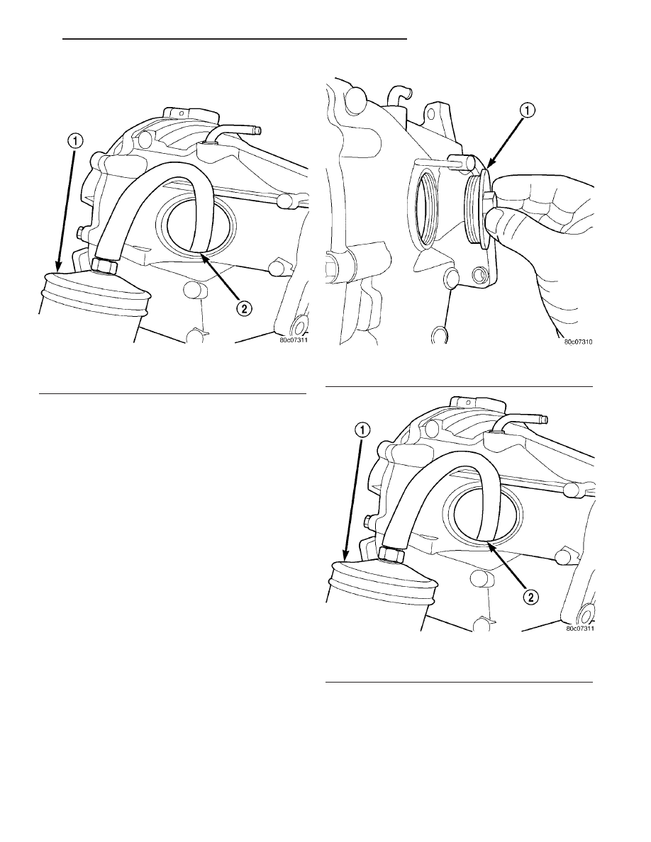
Fig. 7 Removing/Adding PTU Fluid

1 - SUCTION GUN
2 - INSPECTION HOLE

Fig. 8 Inspection Plug

1 - INSPECTION PLUG

Fig. 9 Adding Fluid to PTU

1 - SUCTION GUN
2 - INSPECTION HOLE

RS

POWER TRANSFER UNIT

21 - 5

POWER TRANSFER UNIT (Continued)

(4) Remove propeller shaft assembly (Fig. 10).

(Refer to 3 - DIFFERENTIAL & DRIVELINE/PRO-
PELLER SHAFT - REMOVAL)

(5) Remove cradle plate (Fig. 11).

(6) Remove the Power Transfer Unit mounting

bracket bolts at the rear of the unit (Fig. 12).

(7) Remove the right outboard support bracket and

bolts near the right axle shaft.

(8) Remove the four mounting bolts for the P.T.U.

(Fig. 13)and (Fig. 14).

(9) Remove P.T.U. assembly from vehicle.

INSTALLATION

(1) To install, reverse removal procedure. Check

transaxle fluid and P.T.U. fluid and fill to level.

(2) Refer to the Specifications section for the

proper torque specifications.

ADJUSTMENTS

OUTPUT FLANGE SHIM SELECTION

This procedure is used when the output flange is

replaced. Replacement of the output flange requires
installation of the correct size shim to maintain bear-
ing preload. The shim must protrude from the
new output flange the same distance that the
original

shim

protruded

from

the

original

flange.

(1) Stand the original output flange on end with

shim side pointing up.

(2) Place original shim into groove in top of flange.
(3) Place a straight edge across the shim.

Fig. 10 Driveshaft Flange

1 - DRIVESHAFT FLANGE

Fig. 11 Cradle Plate

1 - CRADLE PLATE

Fig. 12 Remove Rear P.T.U Bracket Bolts

1 - P.T.U. MOUNT BRACKET
2 - P.T.U.

Fig. 13 P.T.U. Lower Mounting Bolts

1 - P.T.U.
2 - P.T.U. MOUNTING BOLTS

21 - 6

POWER TRANSFER UNIT

RS

POWER TRANSFER UNIT (Continued)

(4) Using

feeler

gauge,

measure

the

distance

between the straight edge and the top of the flange
(Fig. 15). Record this measurement.

(5) Repeat steps Step 1 through Step 4using the

new flange and the original shim. Record this
measurement.

(6) If measurements are not equal, use a new shim

that protrudes from new output flange. Make sure it
protrudes the same amount.

(7) For Example: The original shim protrudes

0.075 inch from the original output flange. Place the
original shim into the new output flange. The pro-
trusion of the shim in the new flange is 0.085 inch.
This indicates that a 0.010 inch thinner shim is
required to maintain the original protrusion.

(8) Install output flange and torque flange nut to

244 N·m (180 ft. lbs.).

(9) Check the turning torque of the pinion before

installing the rear cover into the P.T.U. The turning
torque should be between 2.0 N·m and 2.5 N·m (17
in. lbs. and 22 in. lbs.).

SPECIFICATIONS

TORQUE

DESCRIPTION

. . . . . . . . . . . . . . . . . . . . TORQUE

End Cover . . . . . . . . . . . . . . . . 28 N·m (250 in. lbs.)
Fill Plug . . . . . . . . . . . . . . . . . 27 N·m (240 in. lbs.)
Flange Nut . . . . . . . . . . . . . . . 162 N·m (120 ft. lbs.)
Inspection Plug . . . . . . . . . . . . 20 N·m (180 in. lbs.)
Rear Cover . . . . . . . . . . . . . . . 28 N·m (250 in. lbs.)
Ring Gear . . . . . . . . . . . . . . . . . 94 N·m (70 ft. lbs.)

Fig. 14 P.T.U. Upper Mounting Bolts

1 - P.T.U. UPPER MOUNTING BOLTS
2 - P.T.U.

Fig. 15 Output Flange Shim Measurement

1 - MEASURE THIS DIMENSION
2 - SHIM
3 - O-RING
4 - OUTPUT FLANGE

RS

POWER TRANSFER UNIT

21 - 7

POWER TRANSFER UNIT (Continued)

SPECIAL TOOLS

SDP POWER TRANSFER UNIT

5049-a Seal Puller

5065 Bearing Installer

6514 Bearing Remover

6522 Bearing Remover

7794-a Bearing Remover

C-4171 Handle

C-4171-2 Handle

C-4657 Seal Installer

MD998200 Intaller

MD998334 Seal Installer

21 - 8

POWER TRANSFER UNIT

RS

POWER TRANSFER UNIT (Continued)


Content   ..  994  995  996  997   ..