Chrysler RG Voyager. Manual - part 953
to the forged steel connecting rods. The piston pins
are a press fit into the connecting rod small bore.
The piston, pin and connecting rod are serviced as an
assembly.
STANDARD PROCEDURE
STANDARD PROCEDURE - FITTING
CONNECTING RODS
The bearing caps are not interchangeable or
reversible, and should be marked at removal to
ensure correct reassembly. The bearing shells must
be
installed
with
the
tangs
inserted
into
the
machined grooves in the rods and caps. Install cap
with the tangs on the same side as the rod. For con-
necting rod bearing fitting (Refer to 9 - ENGINE/EN-
GINE BLOCK/CONNECTING ROD BEARINGS -
STANDARD PROCEDURE). Fit all connecting rods
on one bank until complete.
NOTE: The connecting rod cap bolts should be
examined before reuse. Bolt stretch can be checked
by holding a scale or straight edge against the
threads. If all the threads do not contact the scale
the bolt must be replaced (Fig. 53).
(1) Before installing the nuts or the bolts the
threads should be oiled with engine oil.
(2) Install nuts or bolts finger tight then alter-
nately torque each nut or bolt to assemble the cap
properly.
(3) Tighten the nuts to 54 N·m PLUS 1/4 turn (40
ft. lbs. PLUS 1/4 turn).
(4) Tighten the cracked cap bolts to 28 N·m PLUS
90 degrees (20 ft.lbs.) plus 90 degrees.
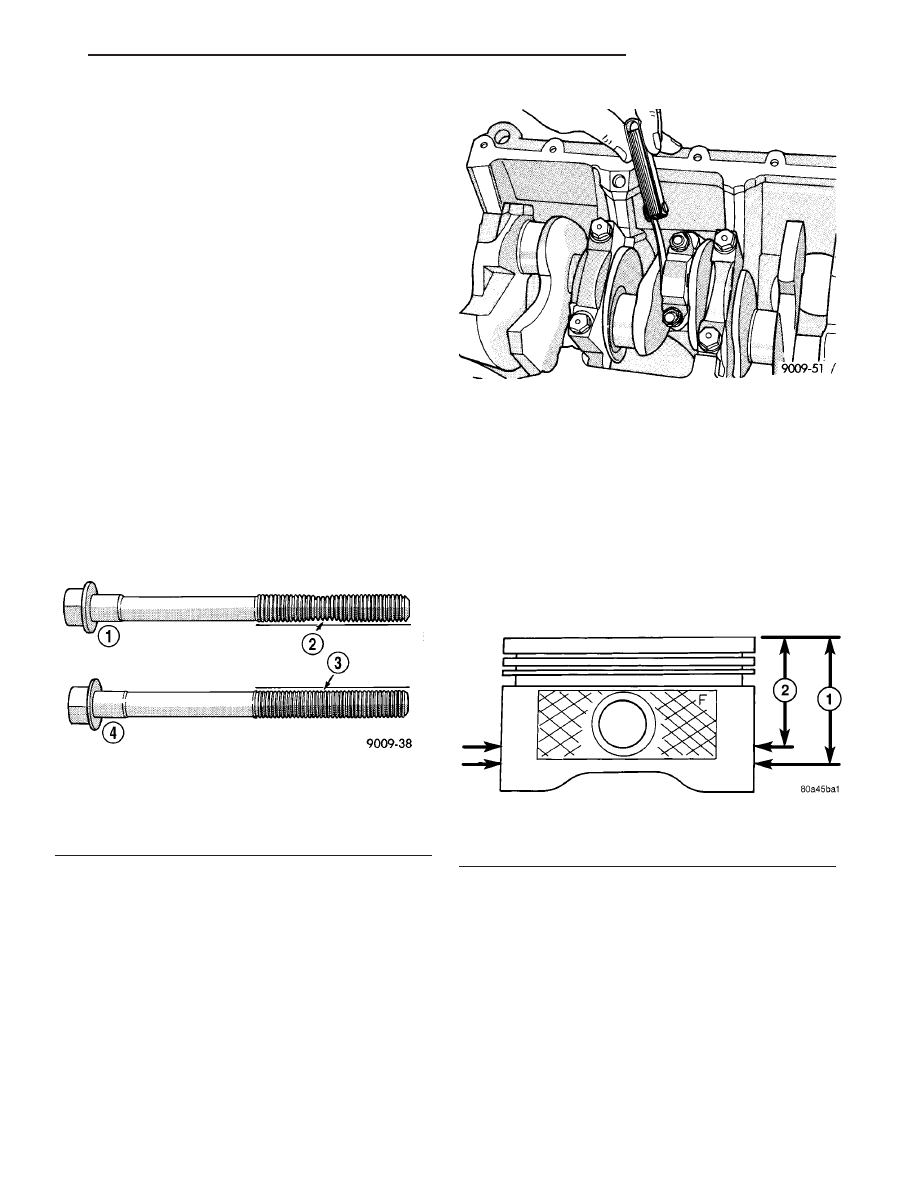
(5) Using a feeler gauge, check connecting rod side
clearance (Fig. 54). Refer to Engine Specifications
(Refer to 9 - ENGINE - SPECIFICATIONS).
STANDARD PROCEDURE - FITTING PISTONS
The piston and cylinder wall must be clean and
dry. Piston diameter should be measured 90 degrees
to piston pin at size location shown in (Fig. 55). Cyl-
inder bores should be measured halfway down the
cylinder bore and transverse to the engine crankshaft
center line shown in (Fig. 56). Refer to Engine Spec-
ifications (Refer to 9 - ENGINE - SPECIFICA-
TIONS). Pistons and cylinder bores should be
measured at normal room temperature, 21°C
(70°F).
REMOVAL
(1) Disconnect negative cable from battery.
(2) Remove the cylinder heads. (Refer to 9 -
ENGINE/CYLINDER HEAD - REMOVAL)
(3) Remove the oil pan. (Refer to 9 - ENGINE/LU-
BRICATION/OIL PAN - REMOVAL)
(4) Remove the top ridge of cylinder bores with a
reliable ridge reamer, if necessary, before removing
pistons from cylinder block. Be sure to keep tops
of pistons covered during this operation. Pis-
tons and connecting rods must be removed
from top of cylinder block. When removing pis-
ton and connecting rod assemblies from the
Fig. 53 Check for Stretched (Necked) Bolts
1 - STRETCHED BOLT
2 - THREADS ARE NOT STRAIGHT ON LINE
3 - THREADS ARE STRAIGHT ON LINE
4 - UNSTRETCHED BOLT
Fig. 54 Checking Connecting Rod Side Clearance
Fig. 55 Piston Measurement Locations - Typical
1 - 39.8 mm (1.56 in. ) 3.3L ENGINE
2 - 33.0 mm (1.29 in.) 3.8L ENGINE
RS
ENGINE 3.3/3.8L
9 - 121
PISTON & CONNECTING ROD (Continued)