Chrysler RG Voyager. Manual - part 744


  Index      Chrysler     Chrysler RG Voyager - service repair manual 2005 year


Search            


Content   ..  742  743  744  745   ..


Chrysler RG Voyager. Manual - part 744


POWER SLIDING DOOR ADJUSTMENT

In order for the power sliding door system to func-

tion

properly

the

door

must

move

freely

and

smoothly. The power sliding door system can accom-
modate for some minor changes in the effort required
to move the door. However, in extreme conditions the
door may need to be mechanically adjusted for proper
fit. (Refer to 23 - BODY/DOORS - SLIDING/SLID-
ING DOOR - ADJUSTMENTS).

If a problem exists with the power sliding door and

it is suspected to be extreme effort, check for proper
door alignment and adjustment first, then check the
door tracks and drive unit for free manual operation.
(Refer to 23 - BODY/DOORS - SLIDING/SLIDING
DOOR - ADJUSTMENTS) for detailed instructions.

LATCH

DESCRIPTION

One power latch is used for each power sliding

door. The latch is located on the trailing edge of the
sliding door assembly (Fig. 3). This power latch
assembly is comprised of many different components
which have the ability to perform the power cinch,
release, lock, unlock and safety related operations.
These components are the door latch, lock/unlock
actuator, cinch/release actuator and child lockout,
pawl, ratchet and handle switches. The pawl and
ratchet switches are used to indicate the primary and
secondary latched positions. The cinch latch also pro-

vides a connection point for the interior handle, exte-
rior handle and hold open latch cables. If any of the
components of the latch assembly are inoperative the
complete power latch assembly must be replaced.

OPERATION

The power latch performs the same operation as a

full manual door latch as well as power cinch,
release, lock and unlock operations. The power latch
mounted actuator cinches the door closed and latches
it in its primary latched position. During a power
close cycle, the power cinch actuator will not operate
until the power sliding door has reached its second-
ary latch position (determined by pawl and ratchet
switches). During a power open cycle, the power
release actuator will stop once the sliding door has
moved from the primary latch position.

The power latch uses inputs from the lock/unlock

actuator, power sliding door control module and child
lockout, pawl, ratchet and handle switches to provide
safe power cinch and release operations. (Refer to 8 -
ELECTRICAL/POWER DOORS - OPERATION) for
additional information.

REMOVAL

(1) Disconnect and isolate the battery negative

cable.

(2) Remove the appropriate side door trim panel,

(Refer to 23 - BODY/DOORS - SLIDING/TRIM
PANEL - REMOVAL).

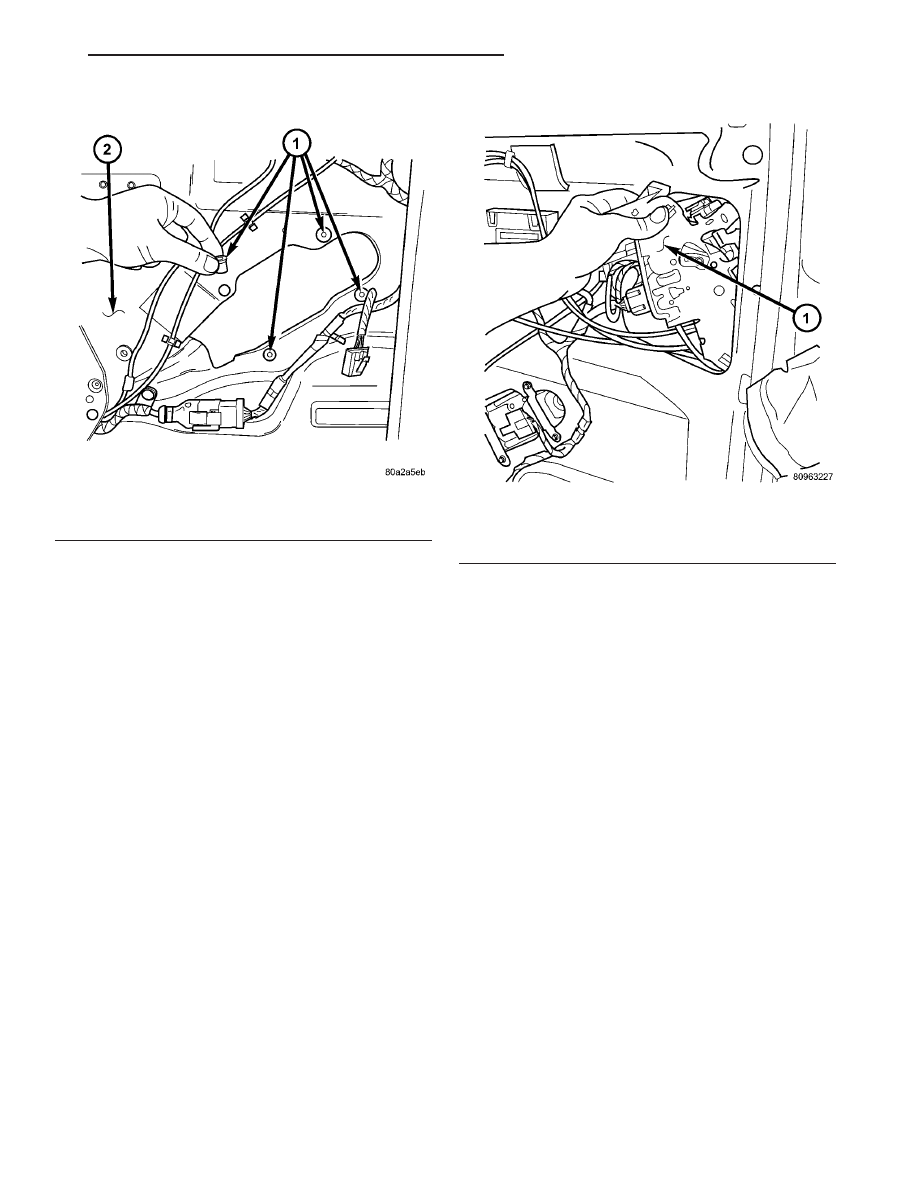
Fig. 2 SIDE DOOR MOTOR PUSH-PIN GROMMETS

1 - PUSH-PIN GROMMETS
2 - SIDE DOOR INNER PANEL

Fig. 3 REMOVING/INSTALLING POWER LATCH IN

SLIDING DOOR

1 - POWER LATCH ASSEMBLY

RS

POWER SLIDING DOOR SYSTEM

8N - 49

POWER SLIDING DOOR SYSTEM (Continued)

(3) Remove the weather shield if necessary.
(4) Open the side door all the way and remove the

door latch retaining bolts (Fig. 4).

(5) Partially close the door and pull the latch

assembly out of the side door inner panel, (Fig. 5).

(6) Disconnect all electrical connectors leading to

the latch assembly.

(7) Disconnect the inside and outside handle cables

from the latch assembly.

(8) Disconnect the hold open latch cable from the

latch assembly.

(9) Disconnect lock actuator link rod from the

latch assembly.

(10) Remove the latch assembly from the vehicle.

INSTALLATION

(1) Position the latch assembly in the vehicle. Be

certain all latch mounted components are installed
on the replacement latch assembly. If not, transfer
components from the old latch to the new latch
assembly, (Fig. 6).

(2) Connect the lock actuator link rod on the latch

assembly.

(3) Connect the hold open latch cable on the latch

assembly.

(4) Connect the inside and outside handle cables

on the latch assembly.

(5) Connect all electrical connectors leading to the

latch assembly.

(6) With assistance from another person, position

the side door and install the door latch retaining
bolts, (Fig. 7). Torque to 10 - 12 N·m (100 in. lbs.).

(7) Install the weathershield if necessary.
(8) Install the appropriate side door trim panel,

(Refer to 23 - BODY/DOORS - SLIDING/TRIM
PANEL - INSTALLATION) for detailed instructions.

Fig. 4 REMOVING LATCH RETAINING BOLTS

1 - LATCH RETAINING BOLTS
2 - SIDE DOOR

Fig. 5 POWER LATCH POSITION & ORIENTATION

1 - POWER LATCH ASSEMBLY

Fig. 6 POWER LATCH POSITION & ORIENTATION

1 - POWER LATCH ASSEMBLY

8N - 50

POWER SLIDING DOOR SYSTEM

RS

LATCH (Continued)

(9) Connect the negative battery cable.

SLIDING DOOR MOTOR

DESCRIPTION

The door motor is located in the center of the

power sliding door (Fig. 8) and is comprised of three
parts. The three parts of the door motor assembly are
the motor, gear reduction and clutch assembly. The
door motor assembly provides the power and torque
to move the sliding door from the open/closed posi-
tion to full closed/open position, after the power
latching mechanism has released.

The door motor is replaced as a complete assembly,

which includes the DC motor, gear reduction and
clutch assemblies.

OPERATION

With the push of a power sliding door command

switch, the power sliding door control module will
signal the latch assembly to release the door from its
primary locked position. The door motor will then
take over to provide the power to open the door to its
full open or closed position. The gear reduction por-
tion of the motor assembly reduces the speed of the
motor from 5800 to 260 rpm and also increases the
torque to the lower drive unit. The clutch portion of
the motor assembly engages the motor to drive the
door under power and disengages it so the door can
be moved easily under manual operation.

REMOVAL

(1) Disconnect and isolate the battery negative

cable.

(2) Remove the door trim panel from the appropri-

ate door, (Refer to 23 - BODY/DOORS - SLIDING/
TRIM PANEL - REMOVAL).

(3) Remove the water shield as necessary to gain

access to motor assembly.

(4) Remove retaining clip holding flex drive assem-

bly to the motor (Fig. 9). Pull flex drive cable straight
out of the motor assembly.

(5) Disconnect door motor electrical connector.
(6) Using a trim stick (special tool #C-4755) or

equivalent, gently pry out push-pin fasteners retain-
ing the door motor.

(7) Remove the door motor assembly from the

vehicle.

INSTALLATION

(1) Position the door motor assembly on the door

inner panel.

(2) Install the push-pin fasteners retaining the

motor assembly to the power sliding door.

Fig. 7 REMOVING LATCH RETAINING BOLTS

1 - LATCH RETAINING BOLTS
2 - SIDE DOOR

Fig. 8 POWER SLIDING DOOR COMPONENTS

1 - POWER SLIDING DOOR CONTROL MODULE
2 - MODULE RETAINING SCREW
3 - MODULE ELECTRICAL CONNECTORS
4 - DOOR MOTOR ASSEMBLY
5 - FLEX DRIVE ASSEMBLY
6 - DOOR MOTOR RETAINING FASTENERS
7 - DOOR MOTOR ELECTRICAL CONNECTOR

RS

POWER SLIDING DOOR SYSTEM

8N - 51

LATCH (Continued)

NOTE: Push in on the push-pins at the clutch hous-
ing (plastic side) until you hear one click. Push in
on the push-pin fasteners at the motor mount
(sheet metal side) until you hear two clicks. This
assures proper installation/attachment of the motor
to the sliding door.

(3) Install the flex shaft by lining up the square

shaped drive shaft with the corresponding hole in the
door motor drive unit and push straight in.

(4) Install the E-clip to secure flex-shaft.
(5) Install the weather shield as necessary.
(6) Install the door trim panel on the sliding door,

(Refer to 23 - BODY/DOORS - SLIDING/TRIM
PANEL - INSTALLATION) for the procedure.

(7) Connect the battery negative cable.

FULL OPEN SWITCH

DESCRIPTION

The full open switch is located in the hold open

latch (Fig. 10) under the sliding door lower hinge.
When the power sliding door control module receives
a ground signal input from the full open switch, and
as long as the cinching latch actuator is not in power
mode or the handle switch is open, the signal indi-
cates that the door is at the full open position.

The full open switch is incorporated into the hold

open latch. If the full open switch is inoperative, the
entire hold open latch assembly must be replaced.

OPERATION

The full open switch is triggered by a pawl lever in

the hold open latch. When the full open switch is
closed (circuit to ground) the ratchet has engaged on
the hold open striker and the pawl lever has engaged
on the ratchet, locking the latch from opening and
holding the door in the full open position.

B-PILLAR SWITCH

DESCRIPTION

The B-pillar switches are located on the interior of

the vehicle, on the B-pillar trim panels. These
switches serve as an open and close command switch
for the appropriate power sliding door.

OPERATION

When the B-pillar switch is depressed a signal is

sent to the Body Control Module (BCM), this signal
is then sent to the power sliding door control module,
telling it to start a power open or close cycle. The
child lockout feature must be disabled and the slid-
ing door must be unlocked in order for the B-pillar
switch to function.

Fig. 9 FLEX DRIVE RETAINING CLIP

1 - FLEX DRIVE CABLE RETAINING CLIP
2 - FLEX DRIVE CABLE
3 - DOOR MOTOR ASSEMBLY

Fig. 10 FULL OPEN SWITCH POSITION &

ORIENTATION

1 - HOLD OPEN LATCH ASSEMBLY
2 - HOLD OPEN LATCH CABLE
3 - FULL OPEN SWITCH

8N - 52

POWER SLIDING DOOR SYSTEM

RS

SLIDING DOOR MOTOR (Continued)


Content   ..  742  743  744  745   ..