Chrysler RG Voyager. Manual - part 688


  Index      Chrysler     Chrysler RG Voyager - service repair manual 2005 year


Search            


Content   ..  686  687  688  689   ..


Chrysler RG Voyager. Manual - part 688


(9) Remove timing belt idler pulley.
(10) Hold camshaft sprocket with Special tool

C-4687 and adaptor C-4687-1 while removing bolt.
Remove both cam sprockets.

(11) Remove the timing belt rear cover (Refer to 9

- ENGINE/VALVE TIMING/TIMING BELT COV-
ER(S) - REMOVAL).

(12) Remove the generator and bracket (Fig. 23).
(13) Remove water pump to engine attaching

screws (Fig. 24).

CLEANING

Clean gasket mating surfaces as necessary.

INSPECTION

Replace water pump body assembly if it has any of

these defects:

(1) Cracks or damage on the body.
(2) Coolant leaks from the shaft seal, evident by

wet coolant traces on the pump body.

(3) Loose or rough turning bearing.
(4) Impeller rubs either the pump body or the

engine block.

(5) Impeller loose or damaged.
(6) Sprocket or sprocket flange loose or damaged.

INSTALLATION

(1) Install new O-ring gasket in water pump body

O-ring locating groove (Fig. 25).

CAUTION: Make sure O-ring is properly seated in
water pump groove before tightening screws. An
improperly located O-ring may be damaged and
cause a coolant leak.

(2) Assemble pump body to block and tighten

screws to 12 N·m (105 in. lbs.) (Fig. 24). Pressurize
cooling system to 103.4 Kpa (15 psi) with pressure
tester and check water pump shaft seal and O-ring
for leaks.

(3) Rotate pump by hand to check for freedom of

movement.

(4) Install the timing belt rear cover (Refer to 9 -

ENGINE/VALVE TIMING/TIMING BELT COVER(S)
- INSTALLATION).

(5) Install camshaft sprockets and torque bolts to

101 N·m (75 ft. lbs.) while holding camshaft sprocket
with Special tool C-4687 and adaptor C-4687-1.

(6) Install timing belt idler pulley and torque

mounting bolt to 61 N·m (45 ft. lbs.).

(7) Install the timing belt (Refer to 9 - ENGINE/

VALVE TIMING/TIMING BELT AND SPROCKET(S)
- INSTALLATION).

(8) Install the generator mount bracket. (Fig. 23)
(9) Install the generator.
(10) Install right engine mount bracket and engine

mount (Refer to 9 - ENGINE/ENGINE MOUNTING/
RIGHT MOUNT - INSTALLATION).

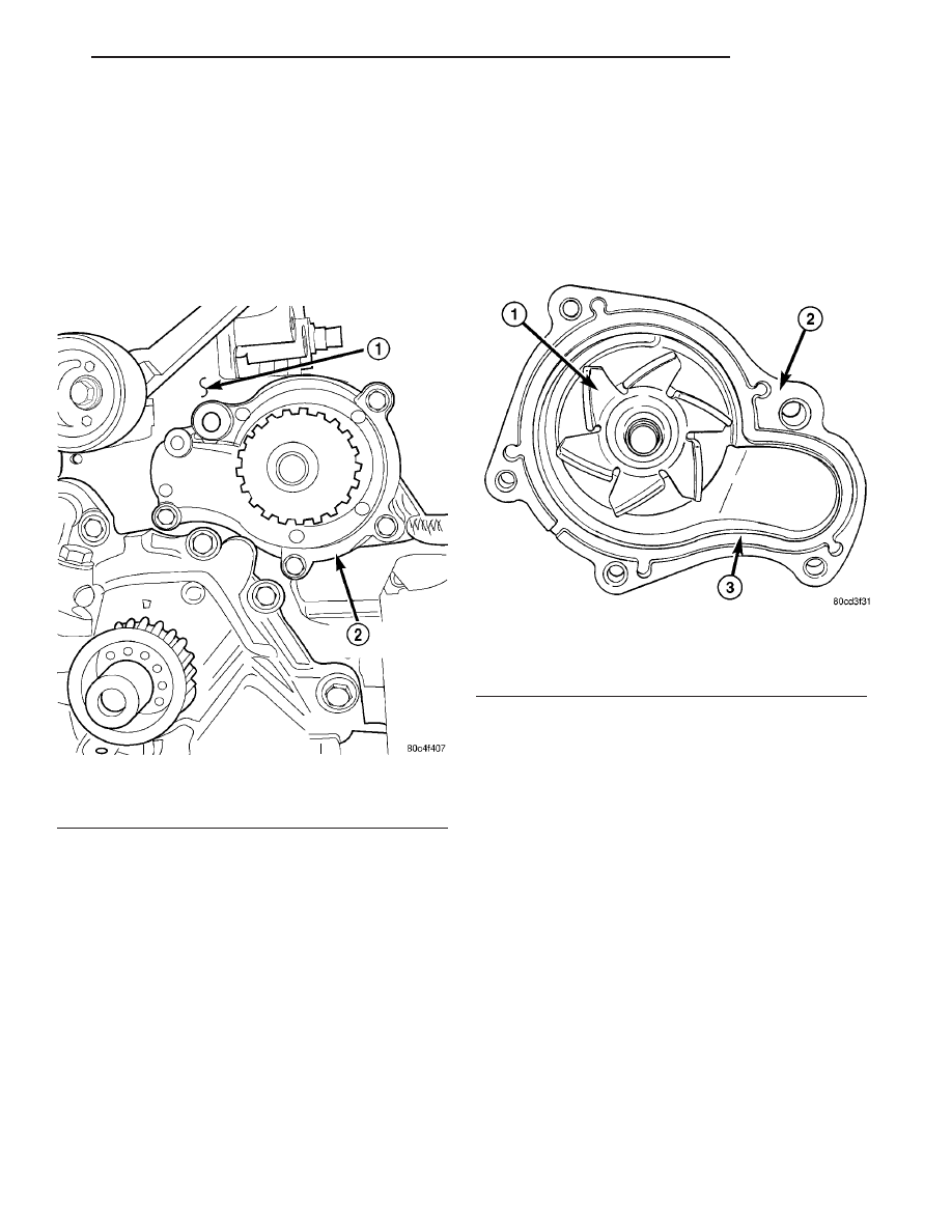
Fig. 24 Water Pump - 2.4L

1 - CYLINDER BLOCK
2 - WATER PUMP

Fig. 25 Water Pump Body

1 - IMPELLER
2 - WATER PUMP BODY
3 - O-RING LOCATING GROOVE

RS

ENGINE

7 - 33

WATER PUMP - 2.4L (Continued)

(11) Fill the cooling system (Refer to 7 - COOLING

- STANDARD PROCEDURE).

(12) Install the accessory drive belts (Refer to 7 -

COOLING/ACCESSORY

DRIVE/DRIVE

BELTS

-

INSTALLATION).

(13) Lower vehicle and connect battery cable.

WATER PUMP - 3.3/3.8L

DESCRIPTION

The water pump has a die-cast aluminum body

and a plastic impeller. It bolts directly to the timing
chain case cover, using a rubber seal for sealing (Fig.
26). It is driven by the accessory drive belt.

REMOVAL

(1) Drain the cooling system. (Refer to 7 - COOL-

ING - STANDARD PROCEDURE)

(2) Remove the accessory drive belt shield.
(3) Remove the accessory drive belt. (Refer to 7 -

COOLING/ACCESSORY

DRIVE/DRIVE

BELTS

-

REMOVAL)

(4) Remove water pump pulley bolts (Fig. 26).

NOTE: To remove the water pump pulley, it MUST
first be positioned between water pump housing
and drive hub. The pulley can then be removed with
the water pump assembly.

(5) Rotate pulley until openings in pulley align

with water pump drive hub spokes (Fig. 27). Move
pulley inward between pump housing and hub (Fig.
27).

(6) Position pulley to allow access to water pump

mounting bolts. Remove water pump mounting bolts
(Fig. 28).

(7) Remove water pump with the pulley loosely

positioned between hub and the pump body.

(8) Remove and discard the seal.
(9) Clean seal groove and sealing surfaces on

pump and timing chain case cover. Take care not to
scratch or gouge sealing surfaces.

CLEANING

Clean gasket mating surfaces as necessary.

Fig. 26 Water Pump - 3.3/3.8L Engine

1 - WATER PUMP
2 - PULLEY - WATER PUMP
3 - BOLT - PULLEY
4 - BOLT - WATER PUMP
5 - SEAL - WATER PUMP

Fig. 27 Water Pump Pulley Positioning

1 - HUB - WATER PUMP
2 - PULLEY - WATER PUMP

Fig. 28 Water Pump Bolts - 3.3/3.8L Engine (Shown

Without Pulley)

1 - WATER PUMP
2 - BOLTS

7 - 34

ENGINE

RS

WATER PUMP - 2.4L (Continued)

INSPECTION

Replace the water pump if it has any of the follow-

ing defects.

(1) Damage or cracks on the pump body.
(2) Coolant leaks; this will be evident by a wet

stream of coolant running down the pump body and
components below. A thin stain below the weep hole
reservoir slot (Fig. 29) is considered normal opera-
tion.

(3) Impeller rubs inside of chain case cover.
(4) Excessively loose or rough turning bearing.

NOTE: A weepage stain that is black, brown, or grey
is considered normal, if it is dry. If the weep
appears wet; pressure test the cooling system at
15–18 psi and observe the weep area. If weep area
remains unchanged, do not replace the water pump
for this condition. Replace the water pump, if a
steady flow of engine coolant is evident from the
weep hole/reservoir slot (Fig. 29) (shaft seal failure).
Be sure to perform a thorough analysis before
replacing water pump.

INSTALLATION

(1) Install new seal into water pump housing

groove (Fig. 30).

NOTE: The water pump pulley MUST be positioned
loosely between the pump housing and drive hub
BEFORE water pump installation.

(2) Position the water pump pulley loosely between

pump housing and drive hub (Fig. 27).

(3) Install water pump and pulley to the timing

chain case cover (Fig. 26). Tighten water pump bolts
to 12 N·m (105 in. lbs.).

(4) Position pulley on water pump hub. Install

bolts and tighten to 28 N·m (250 in. lbs.) (Fig. 26).

(5) Rotate pump by hand to check for freedom of

movement.

(6) Install the accessory drive belt. (Refer to 7 -

COOLING/ACCESSORY

DRIVE/DRIVE

BELTS

-

INSTALLATION)

(7) Install drive belt shield.
(8) Fill the cooling system. (Refer to 7 - COOLING

- STANDARD PROCEDURE)

Fig. 29 Water Pump Inspection - 3.3/3.8L Engine

Fig. 30 Water Pump Seal

1 - WATER PUMP HOUSING
2 - SEAL
3 - IMPELLER

RS

ENGINE

7 - 35

WATER PUMP - 3.3/3.8L (Continued)

WATER PUMP INLET TUBE -
2.4L

DESCRIPTION

The 2.4L engine uses a metal tube to connect the

engine block to the lower radiator hose and heater
return (Fig. 31). The tube has an O-ring for block to
tube sealing and bolts attach the tube to the engine
block.

REMOVAL

(1)

Drain the cooling system. (Refer to 7 - COOL-

ING - STANDARD PROCEDURE)

(2) Remove radiator upper hose to access the hose

connections at the inlet tube.

(3) Remove radiator lower (Fig. 7) and heater

hoses from the inlet tube (Fig. 32).

(4)

Remove the two fasteners that hold the inlet

tube to the block.

(5)

Rotate tube while removing the tube from the

engine block.

INSTALLATION

(1) Inspect the O-ring for damage before installing

the tube into the cylinder block (Fig. 31).

(2) Lube O-ring with coolant and install inlet tube

into the cylinder block opening (Fig. 31).

(3) Install the two inlet tube fasteners and tighten

to 12 N·m (105 in. lbs.).

(4) Connect the radiator lower hose (Fig. 7) and

heater hose to inlet tube (Fig. 32).

(5) Install the radiator upper hose.
(6) Fill the cooling system. (Refer to 7 - COOLING

- STANDARD PROCEDURE)

Fig. 31 Water Pump Inlet Tube - 2.4L Engine

1 - O-RING
2 - WATER PUMP INLET TUBE

Fig. 32 Water Pump Inlet Tube Hose Connections

1 - WATER PUMP INLET TUBE
2 - HOSE - HEATER RETURN
3 - COOLANT INLET

7 - 36

ENGINE

RS


Content   ..  686  687  688  689   ..