Chrysler RG Voyager. Manual - part 683


  Index      Chrysler     Chrysler RG Voyager - service repair manual 2005 year


Search            


Content   ..  681  682  683  684   ..


Chrysler RG Voyager. Manual - part 683


(5) Remove the drive belt (Fig. 10).
(6) Carefully return tensioner to its relaxed posi-

tion.

INSTALLATION

(1) Route and position the drive belt onto all pul-

leys, except for the crankshaft (Fig. 10).

(2) Rotate belt tensioner counterclockwise until

belt can be installed onto the crankshaft pulley (Fig.
9). Slowly release belt tensioner.

(3) Verify belt is properly routed and engaged on

all pulleys (Fig. 11).

(4) Install drive belt shield (Fig. 8) and lower vehi-

cle.

BELT TENSIONER - 3.3/3.8L

REMOVAL

(1) Raise vehicle on hoist.
(2) Remove the drive belt shield.
(3) Remove the drive belt. (Refer to 7 - COOLING/

ACCESSORY DRIVE/DRIVE BELTS - REMOVAL)

(4) Remove the belt tensioner (Fig. 12).

INSTALLATION

(1) Install the belt tensioner and bolt (Fig. 12).

Tighten bolt to 28 N·m (250 in. lbs.).

(2) Install the drive belt. (Refer to 7 - COOLING/

ACCESSORY DRIVE/DRIVE BELTS - INSTALLA-
TION)

(3) Install the drive belt shield.
(4) Lower the vehicle.

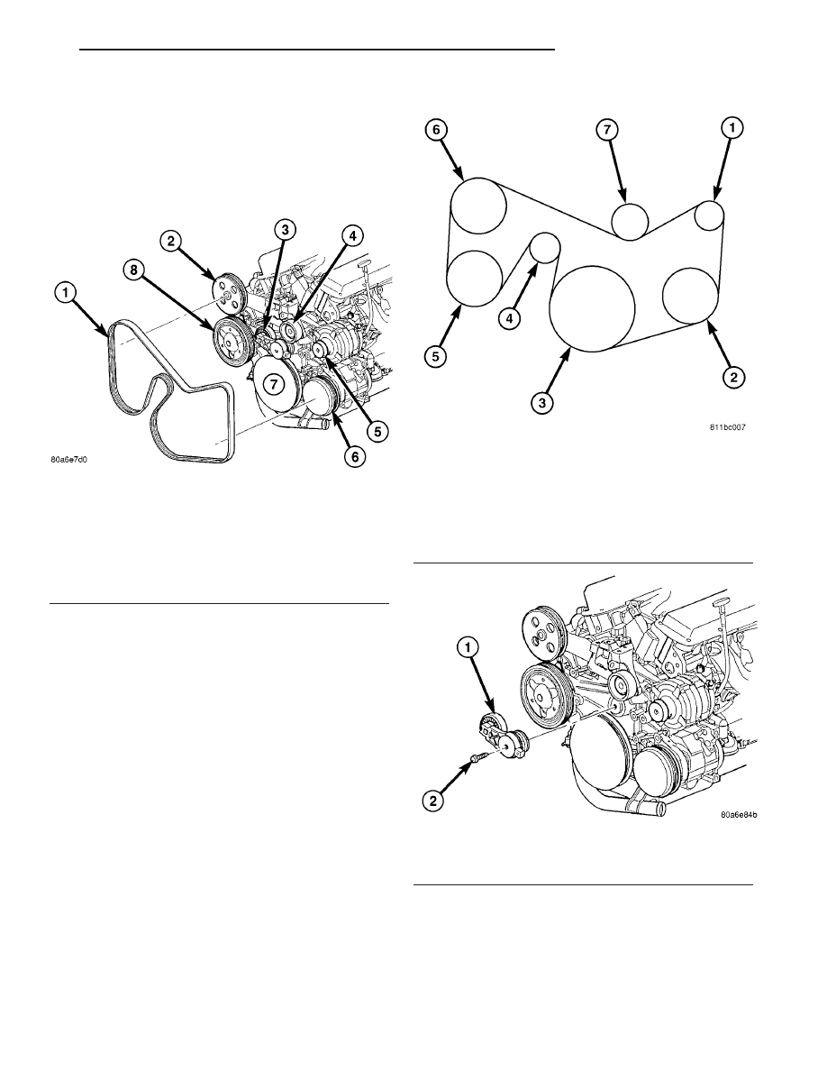
Fig. 10 ACCESSORY DRIVE BELT

1 - DRIVE BELT
2 - POWER STEERING PUMP PULLEY
3 - BELT TENIONER PULLEY
4 - IDLER PULLEY
5 - GENERATOR PULLEY
6 - AIR CONDITIONING COMPRESSOR PULLEY
7 - CRANKSHAFT PULLEY
8 - WATER PUMP PULLEY

Fig. 11 3.3/3.8L Belt Routing

1 - GENERATOR PULLEY
2 - A/C COMPRESSOR PULLEY
3 - CRANKSHAFT PULLEY
4 - TENSIONER PULLEY
5 - WATER PUMP PULLEY
6 - P/S PUMP PULLEY
7 - IDLER PULLEY

Fig. 12 BELT TENSIONER - 3.3/3.8L

1 - BELT TENSIONER
2 - BOLT

RS

ACCESSORY DRIVE

7 - 13

DRIVE BELTS - 3.3/3.8L (Continued)

ENGINE

TABLE OF CONTENTS

page

page

ENGINE

DIAGNOSIS AND TESTING - ENGINE

COOLING SYSTEM

. . . . . . . . . . . . . . . . . . . . 15

CLEANING

. . . . . . . . . . . . . . . . . . . . . . . . . . . . 19

INSPECTION

. . . . . . . . . . . . . . . . . . . . . . . . . . 19

COOLANT

DESCRIPTION - ENGINE COOLANT

. . . . . . . . . 20

DIAGNOSIS AND TESTING - COOLANT

CONCENTRATION TESTING

. . . . . . . . . . . . . 20

STANDARD PROCEDURE - COOLANT

SERVICE

. . . . . . . . . . . . . . . . . . . . . . . . . . . . 20

COOLANT RECOVERY CONTAINER

DESCRIPTION

. . . . . . . . . . . . . . . . . . . . . . . . . 20

OPERATION

. . . . . . . . . . . . . . . . . . . . . . . . . . . 20

DIAGNOSIS AND TESTING - COOLANT

RECOVERY SYSTEM

. . . . . . . . . . . . . . . . . . 21

REMOVAL

. . . . . . . . . . . . . . . . . . . . . . . . . . . . . 21

INSTALLATION

. . . . . . . . . . . . . . . . . . . . . . . . . 21

ENGINE BLOCK HEATER

DESCRIPTION

. . . . . . . . . . . . . . . . . . . . . . . . . 21

OPERATION

. . . . . . . . . . . . . . . . . . . . . . . . . . . 21

DIAGNOSIS AND TESTING - ENGINE BLOCK

HEATER TESTING

. . . . . . . . . . . . . . . . . . . . . 21

REMOVAL

. . . . . . . . . . . . . . . . . . . . . . . . . . . . . 21

INSTALLATION

. . . . . . . . . . . . . . . . . . . . . . . . . 21

ENGINE COOLANT TEMPERATURE SENSOR -

2.4L
DESCRIPTION

. . . . . . . . . . . . . . . . . . . . . . . . . 22

REMOVAL

. . . . . . . . . . . . . . . . . . . . . . . . . . . . . 22

INSTALLATION

. . . . . . . . . . . . . . . . . . . . . . . . . 22

ENGINE COOLANT TEMPERATURE SENSOR -

3.3/3.8L
DESCRIPTION

. . . . . . . . . . . . . . . . . . . . . . . . . 22

REMOVAL

. . . . . . . . . . . . . . . . . . . . . . . . . . . . . 22

INSTALLATION

. . . . . . . . . . . . . . . . . . . . . . . . . 23

ENGINE COOLANT THERMOSTAT

DESCRIPTION

. . . . . . . . . . . . . . . . . . . . . . . . . 23

OPERATION

. . . . . . . . . . . . . . . . . . . . . . . . . . . 23

DIAGNOSIS AND TESTING - ENGINE

COOLANT THERMOSTAT

. . . . . . . . . . . . . . . 24

ENGINE COOLANT THERMOSTAT - 2.4L

REMOVAL

. . . . . . . . . . . . . . . . . . . . . . . . . . . . . 24

INSTALLATION

. . . . . . . . . . . . . . . . . . . . . . . . . 24

ENGINE COOLANT THERMOSTAT - 3.3/3.8L

REMOVAL

. . . . . . . . . . . . . . . . . . . . . . . . . . . . . 24

INSTALLATION

. . . . . . . . . . . . . . . . . . . . . . . . . 25

RADIATOR

REMOVAL

. . . . . . . . . . . . . . . . . . . . . . . . . . . . . 26

INSTALLATION

. . . . . . . . . . . . . . . . . . . . . . . . . 26

RADIATOR DRAINCOCK

REMOVAL

. . . . . . . . . . . . . . . . . . . . . . . . . . . . . 27

INSTALLATION

. . . . . . . . . . . . . . . . . . . . . . . . . 27

RADIATOR PRESSURE CAP

DESCRIPTION

. . . . . . . . . . . . . . . . . . . . . . . . . 27

OPERATION

. . . . . . . . . . . . . . . . . . . . . . . . . . . 27

DIAGNOSIS AND TESTING

DIAGNOSIS AND TESTING - COOLING

SYSTEM PRESSURE CAP TESTING . . . . . . . 28

DIAGNOSIS AND TESTING - RADIATOR

CAP TO FILLER NECK SEAL . . . . . . . . . . . . . 28

CLEANING

. . . . . . . . . . . . . . . . . . . . . . . . . . . . 28

INSPECTION

. . . . . . . . . . . . . . . . . . . . . . . . . . 29

RADIATOR FAN

DESCRIPTION

. . . . . . . . . . . . . . . . . . . . . . . . . 29

OPERATION

. . . . . . . . . . . . . . . . . . . . . . . . . . . 29

DIAGNOSIS AND TESTING - RADIATOR FAN

MOTOR

. . . . . . . . . . . . . . . . . . . . . . . . . . . . . 30

REMOVAL

. . . . . . . . . . . . . . . . . . . . . . . . . . . . . 30

INSTALLATION

. . . . . . . . . . . . . . . . . . . . . . . . . 30

RADIATOR FAN RELAY

DESCRIPTION

. . . . . . . . . . . . . . . . . . . . . . . . . 31

OPERATION

. . . . . . . . . . . . . . . . . . . . . . . . . . . 31

REMOVAL

. . . . . . . . . . . . . . . . . . . . . . . . . . . . . 31

INSTALLATION

. . . . . . . . . . . . . . . . . . . . . . . . . 31

WATER PUMP - 2.4L

DESCRIPTION

. . . . . . . . . . . . . . . . . . . . . . . . . 32

REMOVAL

. . . . . . . . . . . . . . . . . . . . . . . . . . . . . 32

CLEANING

. . . . . . . . . . . . . . . . . . . . . . . . . . . . 33

INSPECTION

. . . . . . . . . . . . . . . . . . . . . . . . . . 33

INSTALLATION

. . . . . . . . . . . . . . . . . . . . . . . . . 33

WATER PUMP - 3.3/3.8L

DESCRIPTION

. . . . . . . . . . . . . . . . . . . . . . . . . 34

REMOVAL

. . . . . . . . . . . . . . . . . . . . . . . . . . . . . 34

CLEANING

. . . . . . . . . . . . . . . . . . . . . . . . . . . . 34

INSPECTION

. . . . . . . . . . . . . . . . . . . . . . . . . . 35

INSTALLATION

. . . . . . . . . . . . . . . . . . . . . . . . . 35

WATER PUMP INLET TUBE - 2.4L

DESCRIPTION

. . . . . . . . . . . . . . . . . . . . . . . . . 36

REMOVAL

. . . . . . . . . . . . . . . . . . . . . . . . . . . . . 36

INSTALLATION

. . . . . . . . . . . . . . . . . . . . . . . . . 36

WATER PUMP INLET TUBE - 3.3/3.8L

REMOVAL

. . . . . . . . . . . . . . . . . . . . . . . . . . . . . 37

INSTALLATION

. . . . . . . . . . . . . . . . . . . . . . . . . 37

7 - 14

ENGINE

RS

ENGINE

DIAGNOSIS AND TESTING - ENGINE COOLING
SYSTEM

Establish what driving condition caused the cooling

system complaint. The problem may be caused by an
abnormal load on the system such as the following:
prolonged idle, very high ambient temperature, slight
tail wind at idle, slow traffic speed, traffic jam, high
speed, steep grade.

DRIVING TECHNIQUES

To avoid overheating the cooling system:
(1) Idle with A/C off when temperature gauge is at

end of normal range.

(2) Do not increase engine speed for more air flow

and coolant flow because the electric motor fan sys-
tems are not responsive to engine RPM. The added
cooling from higher coolant flow rate is more than
offset by increased heat rejection (engine heat added
to coolant).

TRAILER TOWING

Consult the owner’s manual under Trailer Towing

and do not exceed specified limits.

VISUAL INSPECTION

If the cooling system problem is not caused by a

driving condition, perform a visual inspection to
determine if there was a recent service or accident
repair, including the following:

• Loose/damaged water pump drive belt

• Incorrect cooling system refilling (trapped air or

low level)

• Brakes possibly dragging

• Damaged hoses

• Loose/damaged hose clamps

• Damaged/incorrect engine thermostat

• Damaged cooling fan motor, fan blade and fan

shroud

• Damaged head gasket

• Damaged water pump

• Damaged radiator

• Damaged coolant recovery system

• Damaged heater core

• Open/shorted electrical circuits
If the visual inspection reveals none of the above

as cause for a cooling system complaint, refer to the
following diagnostic charts.

COOLING SYSTEM DIAGNOSIS CHART

CONDITION

POSSIBLE CAUSES

CORRECTION

PRESSURE CAP IS BLOWING
OFF STEAM AND/OR COOLANT.
TEMPERATURE GAUGE READING
MAY BE ABOVE NORMAL BUT
NOT HIGH. COOLANT LEVEL MAY
BE HIGH IN COOLANT RESERVE/
OVERFLOW TANK.

1. Pressure relief valve in radiator
cap is defective, or was not
properly seated.

1. Check condition of radiator cap
and cap seal. (Refer to 7 -
COOLING/ENGINE/RADIATOR
PRESSURE CAP - DIAGNOSIS
AND TESTING) Replace cap as
necessary.

2. Incorrect cap was installed.

2. Replace cap as necessary.

3. Incorrect coolant mixture.

3. Check concentration level of the
coolant. (Refer to 7 - COOLING/
ENGINE/COOLANT - DIAGNOSIS
AND TESTING) Adjust the ethylene
glycol-to-water ratio as required.

COOLANT LOSS TO THE
GROUND WITHOUT PRESSURE
CAP BLOWOFF. GAUGE IS
READING HIGH OR HOT.

1. Coolant leaks in radiator, cooling
system hoses, water pump or
engine.

1. Pressure test and repair as
necessary. (Refer to 7 - COOLING -
DIAGNOSIS AND TESTING)

RS

ENGINE

7 - 15

CONDITION

POSSIBLE CAUSES

CORRECTION

DETONATION OR PRE-IGNITION
(NOT CAUSED BY IGNITION
SYSTEM). GAUGE MAY NOT BE
READING HIGH.

1. Engine overheating.

1. Check reason for overheating
and repair as necessary.

2. Freeze point of coolant not
correct. Mixture too concentrated or
too diluted.

2. Check concentration level of the
coolant. (Refer to 7 - COOLING/
ENGINE/COOLANT - DIAGNOSIS
AND TESTING) Adjust the ethylene
glycol-to-water ratio as required.

3. Incorrect cooling system
pressure cap.

3. Install correct pressure cap.

HOSE(S) COLLAPSE AS ENGINE
COOLS DOWN.

1. Vacuum created in cooling
system on engine cool-down is not
being relieved through coolant
recovery system.

1. (a) Pressure cap relief valve
stuck. (Refer to 7 - COOLING/
ENGINE/RADIATOR PRESSURE
CAP - DIAGNOSIS AND TESTING)
Replace as necessary.

(b) Hose between the radiator and
overflow container is plugged or
pinched. Clean and repair as
necessary.

(c) Vent at coolant reserve/overflow
container is plugged. Clean vent
and repair as necessary.

(d) Reserve/overflow container is
internally blocked. Clean and repair
as necessary.

INADEQUATE AIR CONDITIONER
PERFORMANCE (COOLING
SYSTEM SUSPECTED).

1. Radiator and/or A/C condenser is
restricted, obstructed, or dirty
(insects, leaves, etc.).

1. Remove restriction and/or clean
as necessary.

2. Electrical radiator fan not
operating when A/C is operated.

2. For test procedure (Refer to
appropriate Diagnostic Information).
Repair as necessary.

3. Engine is overheating (heat may
be transferred from radiator to A/C
condenser). High underhood
temperatures due to engine
overheating may also transfer heat
to A/C components.

3. Correct overheating condition.

4. All models are equipped with air
seals at the radiator and/or A/C
condenser. If these seals are
missing or damaged, not enough
air flow will be pulled through the
radiator and A/C condenser.

4. Check for missing or damaged air
seals and repair as necessary.

INADEQUATE HEATER
PERFORMANCE.

1. Check for a Diagnostic trouble
code (DTC).

1. For procedures, (Refer to
appropriate Diagnostic Information).
Repair as necessary.

2. Coolant level low.

2. (Refer to 7 - COOLING -
STANDARD PROCEDURE) Repair
as necessary.

7 - 16

ENGINE

RS

ENGINE (Continued)


Content   ..  681  682  683  684   ..