Chrysler RG Voyager. Manual - part 680


  Index      Chrysler     Chrysler RG Voyager - service repair manual 2005 year


Search            


Content   ..  678  679  680  681   ..


Chrysler RG Voyager. Manual - part 680


COOLING

TABLE OF CONTENTS

page

page

COOLING

DESCRIPTION

DESCRIPTION - COOLING SYSTEM

. . . . . . . . 1

DESCRIPTION - HOSE CLAMPS

. . . . . . . . . . . 1

OPERATION

OPERATION - COOLING SYSTEM

. . . . . . . . . 2

OPERATION - HOSE CLAMPS

. . . . . . . . . . . . 2

DIAGNOSIS AND TESTING

DIAGNOSIS AND TESTING - COOLING

SYSTEM LEAK TEST . . . . . . . . . . . . . . . . . . . . 2

DIAGNOSIS AND TESTING - COOLING

SYSTEM FLOW CHECK . . . . . . . . . . . . . . . . . 3

DIAGNOSIS AND TESTING - COOLING

SYSTEM AERATION . . . . . . . . . . . . . . . . . . . . 3

DIAGNOSIS AND TESTING - COOLING

SYSTEM DEAERATION . . . . . . . . . . . . . . . . . . 4

STANDARD PROCEDURE

STANDARD PROCEDURE - COOLING

SYSTEM DRAINING . . . . . . . . . . . . . . . . . . . . 4

STANDARD PROCEDURE - COOLING

SYSTEM FILLING . . . . . . . . . . . . . . . . . . . . . . 4

STANDARD PROCEDURE - ADDING

ADDITIONAL COOLANT . . . . . . . . . . . . . . . . . 4

STANDARD PROCEDURE - COOLANT

LEVEL CHECK . . . . . . . . . . . . . . . . . . . . . . . . 4

COOLING SYSTEM CLEANING/REVERSE

FLUSHING . . . . . . . . . . . . . . . . . . . . . . . . . . . . 4

SPECIFICATIONS

ACCESSORY DRIVE BELT TENSION

. . . . . . . 6

TORQUE

. . . . . . . . . . . . . . . . . . . . . . . . . . . . . 6

SPECIAL TOOLS

COOLING SYSTEM

. . . . . . . . . . . . . . . . . . . . . 7

ACCESSORY DRIVE

. . . . . . . . . . . . . . . . . . . . . . . 8

ENGINE

. . . . . . . . . . . . . . . . . . . . . . . . . . . . . . . 14

TRANSMISSION

. . . . . . . . . . . . . . . . . . . . . . . . . 38

COOLING

DESCRIPTION

DESCRIPTION - COOLING SYSTEM

The cooling system components consist of a radia-

tor, electric fan motors, shroud, pressure cap, thermo-
stat, transmission oil cooler, water pump, hoses,
clamps, coolant, and a coolant reserve system to com-
plete the circuit.

DESCRIPTION - HOSE CLAMPS

The cooling system uses spring type hose clamps.

If a spring type clamp replacement is necessary,
replace with the original Mopar

t equipment spring

type clamp.

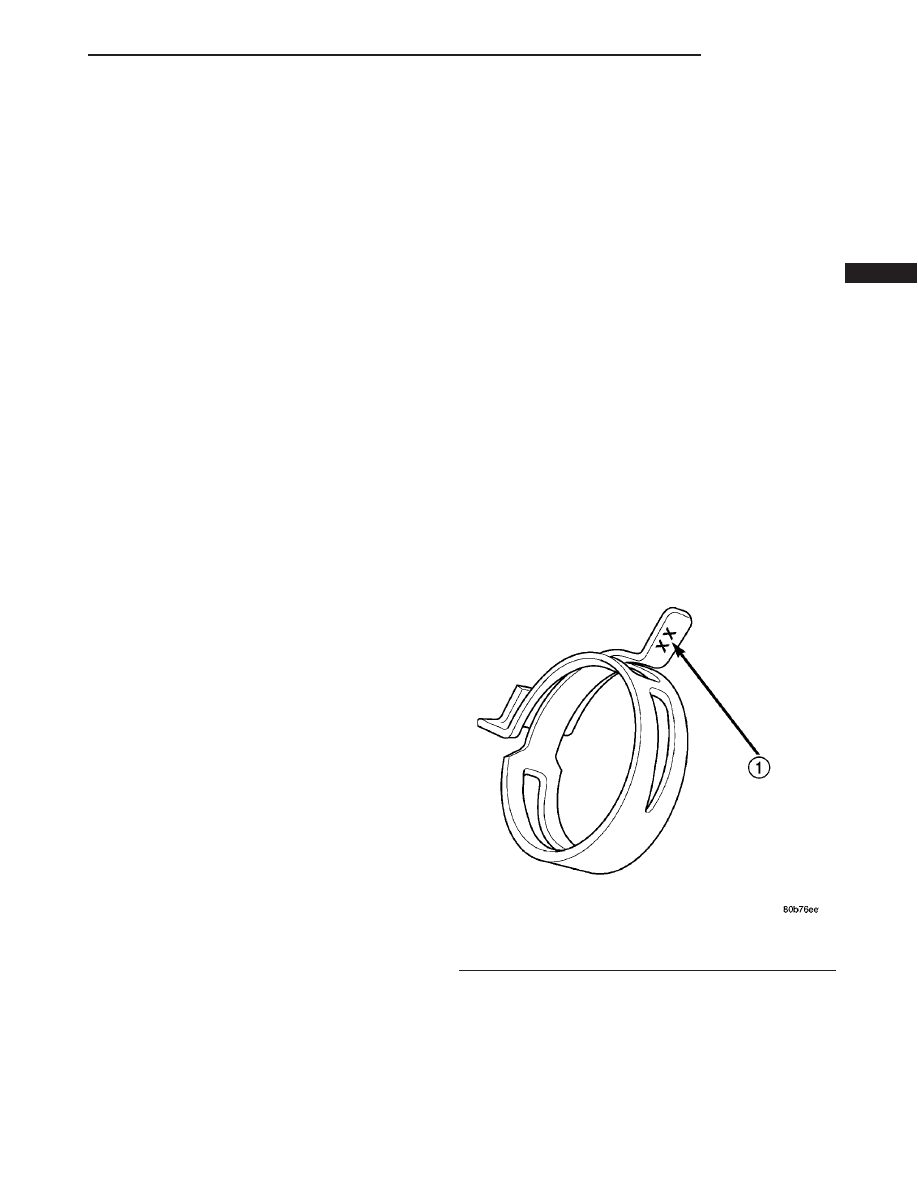
CAUTION: A number or letter is stamped into the
tongue of constant tension clamps. If replacement
is necessary, use only a original equipment clamp
with matching number or letter (Fig. 1).

Fig. 1 Spring Clamp Size Location

1 - SPRING CLAMP SIZE LOCATION

RS

COOLING

7 - 1

OPERATION

OPERATION - COOLING SYSTEM

The engine cooling systems primary purpose is to

maintain engine temperature in a range that will
provide satisfactory engine performance and emission
levels under all expected driving conditions. It also
provides hot water (coolant) for heater performance
and cooling for automatic transmission oil. It does
this by transferring heat from engine metal to cool-
ant, moving this heated coolant to the radiator, and
then transferring this heat to the ambient air.

• When engine is cold: thermostat is closed, cool-

ing system has no flow through the radiator. The
coolant bypass flows through the engine only.

• When engine is warm: thermostat is open, cool-

ing system has bypass flow and coolant flow through
radiator.

Coolant flow circuits for the 2.4L and 3.3/3.8L

engines are shown in (Fig. 2).

OPERATION - HOSE CLAMPS

The spring type hose clamp applies constant ten-

sion on a hose connection. To remove a spring type
hose clamp, use Special Tool 6094 or equivalent, con-
stant tension clamp pliers (Fig. 3) to compress the
hose clamp.

DIAGNOSIS AND TESTING

DIAGNOSIS AND TESTING - COOLING SYSTEM
LEAK TEST

WARNING: THE WARNING WORDS “DO NOT OPEN
HOT” ON THE RADIATOR PRESSURE CAP IS A
SAFETY PRECAUTION. WHEN HOT, PRESSURE
BUILDS UP IN COOLING SYSTEM. TO PREVENT
SCALDING

OR

INJURY,

THE

RADIATOR

CAP

SHOULD NOT BE REMOVED WHILE THE SYSTEM
IS HOT OR UNDER PRESSURE.

Fig. 2 Cooling System Flow

1 - HEATER - REAR (3.3/3.8L OPTIONAL EQUIPMENT)

6 - WATER PUMP

2 - HEATER - FRONT

7 - RADIATOR

3 - ENGINE

8 - COOLANT RECOVERY/RESERVE CONTAINER

4 - THERMOSTAT

9 - COOLANT FLOW - PRESSURE CAP VACUUM

5 - ENGINE OIL COOLER (3.3/3.8L OPTIONAL EQUIPMENT)

10 - COOLANT FLOW - PRESSURE CAP RELIEF

7 - 2

COOLING

RS

COOLING (Continued)

With engine not running, remove radiator pressure

cap and wipe the radiator filler neck sealing seat
clean. The radiator should be full.

Attach the Cooling System Tester 7700 or equiva-

lent to the radiator, as shown in (Fig. 4) and apply
104 kPa (15 psi) pressure. If the pressure drops more
than 13.8 kPa (2 psi) in 2 minutes, inspect all points
for external leaks.

All radiator and heater hoses should be shaken

while at 104 kPa (15 psi), since some leaks occur only
while driving due to engine movement.

If there are no external leaks, after the gauge dial

shows a drop in pressure, detach the tester. Start
engine and run until the thermostat opens, allowing

the coolant to expand. Reattach the cooling system
tester. If the needle on the dial fluctuates it indicates
a combustion leak, usually a head gasket leak.

WARNING: WITH TOOL IN PLACE, PRESSURE WILL
BUILD UP FAST. EXCESSIVE PRESSURE BUILT UP,
BY CONTINUOUS ENGINE OPERATION, MUST BE
RELEASED TO A SAFE PRESSURE POINT. NEVER
PERMIT PRESSURE TO EXCEED 138 kPa (20 psi).

If the needle on the dial does not fluctuate, raise

the engine rpm a few times. If an abnormal amount
of coolant or steam emits from the tailpipe, it may
indicate a coolant leak caused by a faulty head gas-
ket, cracked engine block, or cracked cylinder head.

There may be internal leaks that can be deter-

mined by removing the oil dipstick. If water globules
appear intermixed with the oil it will indicate an
internal leak in the engine. If there is an internal
leak, the engine must be disassembled for repair.

DIAGNOSIS AND TESTING - COOLING SYSTEM
FLOW CHECK

To determine whether coolant is flowing through

the cooling system, use one of the following proce-
dures:

PREFERRED METHOD

WARNING: DO NOT REMOVE THE COOLING SYS-
TEM PRESSURE CAP OR ANY HOSE WITH THE
SYSTEM HOT AND UNDER PRESSURE BECAUSE
SERIOUS BURNS FROM COOLANT CAN OCCUR.

• Remove pressure cap when engine is cold.

Remove small amount of coolant. Idle engine until
thermostat opens. You should observe coolant flow
while looking down the filler neck. Once flow is
detected install the pressure cap. Replace removed
coolant into coolant recovery container.

ALTERNATIVE METHOD

• If engine is cold, idle engine until normal oper-

ating temperature is reached. Feel the upper radiator
hose. If it is hot, coolant is circulating.

DIAGNOSIS AND TESTING - COOLING SYSTEM
AERATION

Low coolant level in a cross flow radiator will

equalize in both tanks with engine off. With engine
at running and at operating temperature, the high
pressure inlet tank runs full and the low pressure
outlet tank drops, resulting in cooling system aera-
tion. Aeration will draw air into the water pump
resulting in the following:

• High reading shown on the temperature gauge.

Fig. 3 Hose Clamp Tool

1 - HOSE CLAMP TOOL 6094
2 - HOSE CLAMP

Fig. 4 Pressure Testing

RS

COOLING

7 - 3

COOLING (Continued)

• Loss of coolant flow through the heater core.

• Corrosion in the cooling system.

• Water pump seal may run dry, increasing the

risk of premature seal failure.

• Combustion gas leaks into the coolant can also

cause the above problems.

DIAGNOSIS AND TESTING - COOLING SYSTEM
DEAERATION

Air can only be removed from the system by gath-

ering under the pressure cap. On the next heat up it
will be pushed past the pressure cap into the coolant
recovery bottle by thermal expansion of the coolant.
It then escapes to the atmosphere in the coolant
recovery bottle and is replaced with coolant on cool
down.

To effectively deaerate the system, multiple ther-

mal cycles of the system may be required.

NOTE: Deaeration does not occur at engine idle—
higher engine speeds are required. Normal driving
will deaerate cooling system.

STANDARD PROCEDURE

STANDARD PROCEDURE - COOLING SYSTEM
DRAINING

WARNING: DO NOT REMOVE OR LOOSEN THE
COOLANT

PRESSURE

CAP,

CYLINDER

BLOCK

DRAIN PLUGS, OR THE DRAINCOCK WHEN THE
SYSTEM

IS

HOT

AND

UNDER

PRESSURE

BECAUSE SERIOUS BURNS FROM THE COOLANT
CAN OCCUR.

(1) Without removing radiator pressure cap

and with system not under pressure, using a
screwdriver, open the draincock. The draincock is
located on the lower left side of radiator.

(2) After the coolant recovery/reserve container is

empty, then remove coolant pressure cap (Fig. 5).

(3) Remove the cylinder block drain plug(s).

STANDARD PROCEDURE - COOLING SYSTEM
FILLING

Remove radiator pressure cap (Fig. 5) and fill sys-

tem, using a 50/50 mix of Mopar

t Antifreeze/Coolant,

5 Year/100,000 Mile Formula and distilled water.

Continue filling system until full. Be careful not

to spill coolant on drive belts or the generator.
For cooling system capacity, (Refer to LUBRICATION
& MAINTENANCE/FLUID CAPACITIES - SPECIFI-
CATIONS).

Fill coolant recovery/reserve container (Fig. 5) to at

least the MAX mark with 50/50 solution. It may be
necessary to add coolant to the recovery/reserve con-
tainer after three or four warm up/cool down cycles
to maintain coolant level between the MAX and MIN
mark. This will allow trapped air to be removed from
the system.

STANDARD PROCEDURE - ADDING
ADDITIONAL COOLANT

The radiator cap should not be removed.

When additional coolant is needed to maintain this
level, it should be added to the coolant recovery/re-
serve container (Fig. 5). Use only 50/50 mix of ethyl-
ene glycol type antifreeze and distilled water. For the
recommeded antifreeze/coolant type (Refer to LUBRI-
CATION

&

MAINTENANCE/FLUID

TYPES

-

DESCRIPTION).

CAUTION: Do not use well water, or suspect water
supply in cooling system. A 50/50 ethylene glycol
and distilled water mix is recommended. For the
recommeded

antifreeze/coolant

type

(Refer

to

LUBRICATION & MAINTENANCE/FLUID TYPES -
DESCRIPTION).

STANDARD PROCEDURE - COOLANT LEVEL
CHECK

NOTE: Do not remove radiator cap for routine cool-
ant level inspections.

The coolant reserve system provides a quick visual

method for determining the coolant level without
removing the radiator cap. With the engine cold
and not running, 
simply observe the level of the
coolant in the recovery/reserve container (Fig. 5). The
coolant level should be between the MIN and MAX
marks.

COOLING SYSTEM CLEANING/REVERSE
FLUSHING

CLEANING

Drain the cooling system and refill with water. Run

the engine with the radiator cap installed until the
upper radiator hose is hot. Stop the engine and drain
the water from system. If the water is dirty, fill the
system with water, run the engine and drain the sys-
tem. Repeat this procedure until the water drains
clean.

REVERSE FLUSHING

Reverse flushing of the cooling system is the forc-

ing of water through the cooling system. This is done

7 - 4

COOLING

RS

COOLING (Continued)


Content   ..  678  679  680  681   ..