Chrysler RG Voyager. Manual - part 650


  Index      Chrysler     Chrysler RG Voyager - service repair manual 2005 year


Search            


Content   ..  648  649  650  651   ..


Chrysler RG Voyager. Manual - part 650


dard equipment on all-wheel drive and all right-hand
drive models. It is optional on other models.

The BR3 system features larger, externally vented

front brake rotors.

Although there are different disc/disc systems, they

are serviced using the same service procedures. Some
specifications differ.

DESCRIPTION - DRUM BRAKES (REAR)

This vehicle’s rear wheel drum brakes are a two-

shoe, internal-expanding type with an automatic
adjuster screw. The automatic adjuster screw is
located directly below the wheel cylinder that is
mounted near the top of the brake assembly (Fig. 9).
These and two brake shoes (and attaching parts) are
mounted to a support plate at each rear wheel. A
brake drum covers each brake assembly.

OPERATION

OPERATION - DISC BRAKES (FRONT)

When the brakes are applied, fluid pressure is sent

to each brake caliper. The pressure at the caliper is
exerted equally against the caliper piston. The pres-
sure applied to the piston is transmitted directly to
the inboard brake shoe. This forces the shoe lining
against the inner surface of the brake rotor. At the
same time, fluid pressure within the caliper piston
bore forces the caliper to slide inward on its guide
pins. This action brings the outboard shoe lining into
contact with the outer surface of the brake rotor.
This pressure on both sides of the brake rotor causes
friction, bringing the vehicle to a stop.

When the brake pedal is released, so is the fluid

pressure. The piston seal inside the caliper is

designed to pull the piston back into the bore of the
caliper when the brake pedal is released (Fig. 10).
This action helps maintain the proper brake shoe-to-
rotor clearance.

As disc brake shoe linings wear, master cylinder

reservoir brake fluid level will drop. Adjust as neces-
sary. Fluid level should always be checked after
replacing shoes.

OPERATION - DISC BRAKES (REAR)

The rear disc brakes operate similarly to front disc

brakes, however, there are some features that require
different service procedures.

DIAGNOSIS AND TESTING - DRUM BRAKE
AUTOMATIC ADJUSTER

The rear drum brakes on this vehicle automatically

adjust when required during the normal operation of
the vehicle every time the brakes are applied. Use
the following procedure to test the operation of the
automatic adjuster.

Place the vehicle on a hoist with a helper in the

driver’s seat to apply the brakes. Remove the access
plug from the adjustment hole in each brake support
plate to provide visual access of the brake adjuster
star wheel.

To eliminate the condition where maximum adjust-

ment of the rear brake shoes does not allow the auto-
matic adjuster to operate when tested, back the star
wheel off approximately 30 notches. It will be neces-
sary to hold the adjuster lever away from the star
wheel to permit this adjustment.

Have the helper apply the brakes. Upon applica-

tion of the brake pedal, the adjuster lever should
move down, turning the adjuster star wheel. Thus, a
definite rotation of the adjuster star wheel can be

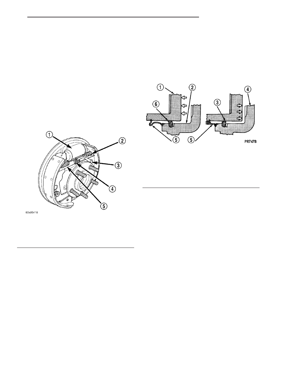
Fig. 9 Drum Brake Assembly (Right Shown)

1 - WHEEL CYLINDER
2 - BRAKE SHOE UPPER RETURN SPRING
3 - AUTOMATIC ADJUSTER LEVER
4 - TENSION CLIP
5 - AUTOMATIC ADJUSTER ASSEMBLY

Fig. 10 Caliper Piston Seal Function For Automatic

Adjustment

1 - PISTON
2 - CYLINDER BORE
3 - PISTON SEAL BRAKE PRESSURE OFF
4 - CALIPER HOUSING
5 - DUST BOOT
6 - PISTON SEAL BRAKE PRESSURE ON

RS

BRAKES - BASE

5 - 13

HYDRAULIC/MECHANICAL (Continued)

observed if the automatic adjuster is working prop-
erly. If one or more adjusters do not function prop-
erly, the respective drum must be removed for
adjuster servicing.

BRAKE LINES

DESCRIPTION - BRAKE TUBES AND HOSES

The brake tubes are steel with a corrosion-resis-

tant nylon coating applied to the external surfaces.
The flex hoses are made of reinforced rubber with fit-
tings at each end.

The primary and secondary brake tubes leading

from the master cylinder to the ABS ICU Hydraulic
Control Unit (HCU) or the non-ABS junction block
have a special flexible section. This flexible section is
required due to cradle movement while the vehicle is
in motion (The ICU and non-ABS junction block are
mounted to the cradle). If replacement of these
lines is necessary, only the original factory
brake line containing the flexible section must
be used
.

OPERATION - BRAKE TUBES AND HOSES

The purpose of the chassis brake tubes and flex

hoses is to transfer the pressurized brake fluid devel-
oped by the master cylinder to the wheel brakes of
the vehicle. The flex hoses are made of rubber to
allow for the movement of the vehicle’s suspension.

INSPECTION - BRAKE TUBES AND HOSES

Flexible rubber hose is used at both front brakes

and at the rear axle. Inspection of brake hoses
should be performed whenever the brake system is
serviced and every 7,500 miles or 12 months, which-
ever comes first (every engine oil change). Inspect
hydraulic brake hoses for surface cracking, scuffing,
or worn spots. If the fabric casing of the rubber hose
becomes exposed due to cracks or abrasions in the
rubber hose cover, the hose should be replaced imme-
diately. Eventual deterioration of the hose can take
place with possible burst failure. Faulty installation
can cause twisting, resulting in wheel, tire, or chassis
interference.

The brake tubing should be inspected periodically

for evidence of physical damage or contact with mov-
ing or hot components.

The flexible brake tube sections used on this vehi-

cle in the primary and secondary tubes from the
master cylinder to the ABS hydraulic control unit
connections must also be inspected. This flexible tub-
ing must be inspected for kinks, fraying and contact
with other components or with the body of the vehi-
cle.

BRAKE PADS/SHOES - FRONT

REMOVAL

REMOVAL - FRONT DISC BRAKE SHOES
(CONTINENTAL TEVES BRAKES)

(1) Raise the vehicle. (Refer to LUBRICATION &

MAINTENANCE/HOISTING - STANDARD PROCE-
DURE).

(2) Remove both front wheel and tire assemblies.
(3) Begin on one side of the vehicle.
(4) Remove the anti-rattle clip from the outboard

side of the caliper and adapter.

(5) Remove the two caliper guide pin bolts.
(6) Remove caliper from caliper adapter and brake

rotor.

CAUTION: Supporting weight of caliper by the flex-
ible brake fluid hose can damage the hose.

(7) Using wire or cord, hang the caliper from the

front strut assembly (Fig. 11). Support the caliper
firmly to prevent weight of caliper from being sup-
ported by the brake fluid hose.

(8) Remove the outboard brake shoe from the cali-

per adapter.

(9) Pull the inboard brake shoe away from the cal-

iper piston until the retaining clip on shoe is free
from the cavity in the caliper piston (Fig. 12).

(10) Repeat the above procedure on other side of

the vehicle.

Fig. 11 Stored Front Disc Brake Caliper

1 - STEERING KNUCKLE
2 - BRAKE FLEX HOSE
3 - CALIPER ASSEMBLY
4 - WIRE HANGER
5 - STRUT ASSEMBLY

5 - 14

BRAKES - BASE

RS

HYDRAULIC/MECHANICAL (Continued)

REMOVAL - FRONT DISC BRAKE SHOES (TRW
BRAKES)

(1) Raise the vehicle. Refer to HOISTING in

LUBRICATION AND MAINTENANCE.

NOTE: Perform Step 2 through Step 5 on each side
of the vehicle.

(2) Remove the front tire and wheel assembly.
(3) Remove the two brake caliper guide pin bolts

(Fig. 13).

(4) Remove the disc brake caliper from the disc

brake adapter and hang out of the way using wire or
a bungee cord. Use care not to overextend the brake
hose when doing this.

(5) Remove the brake shoes from the disc brake

caliper adapter.

CLEANING - DISC BRAKE SHOES

WARNING: DUST AND DIRT ACCUMULATING ON
BRAKE PARTS DURING NORMAL USE MAY CON-
TAIN ASBESTOS FIBERS FROM PRODUCTION OR
AFTERMARKET

BRAKE

LININGS.

BREATHING

EXCESSIVE

CONCENTRATIONS

OF

ASBESTOS

FIBERS CAN CAUSE SERIOUS BODILY HARM.
EXERCISE

CARE

WHEN

SERVICING

BRAKE

PARTS. DO NOT SAND OR GRIND BRAKE LINING
UNLESS EQUIPMENT USED IS DESIGNED TO CON-
TAIN THE DUST RESIDUE. DO NOT CLEAN BRAKE
PARTS

WITH

COMPRESSED AIR

OR

BY DRY

BRUSHING. CLEANING SHOULD BE DONE BY
DAMPENING THE BRAKE COMPONENTS WITH A
FINE MIST OF WATER, THEN WIPING THE BRAKE
COMPONENTS CLEAN WITH A DAMPENED CLOTH.
DISPOSE OF CLOTH AND ALL RESIDUE CONTAIN-
ING ASBESTOS FIBERS IN AN IMPERMEABLE
CONTAINER WITH THE APPROPRIATE LABEL. FOL-
LOW PRACTICES PRESCRIBED BY THE OCCUPA-
TIONAL SAFETY AND HEALTH ADMINISTRATION
(OSHA) AND THE ENVIRONMENTAL PROTECTION
AGENCY (EPA) FOR THE HANDLING, PROCESSING,
AND DISPOSING OF DUST OR DEBRIS THAT MAY
CONTAIN ASBESTOS FIBERS.

INSPECTION - DISC BRAKE SHOES

Visually inspect brake shoes (pads) for uneven lin-

ing wear. Also inspect for excessive lining deteriora-
tion. Check the clearance between the tips of the
wear indicators on the shoes (if equipped) and the
brake rotors.

If a visual inspection does not adequately deter-

mine the condition of the lining, a physical check will
be necessary. To check the amount of lining wear,
remove the disc brake shoes from the calipers.

Measure each brake shoe. The combined brake

shoe and its lining material thickness should be mea-
sured at its thinnest point.

• For front disc brake shoes, when a set of brake

shoes are worn to a thickness of approximately 7.95
mm (5/16 inch), they should be replaced.

• For rear disc brake shoes, when a set of brake

shoes are worn to a thickness of approximately 7.0
mm (9/32 inch), they should be replaced.

• Typically, if front shoes are worn out, both fronts

and rears need to be replaced. Make sure to check
rears.

Fig. 12 Removing Inboard Shoe

1 - INBOARD BRAKE SHOE
2 - HANGER WIRE
3 - CALIPER ASSEMBLY
4 - RETAINING CLIP
5 - PISTON

Fig. 13 Brake Caliper Mounting (Typical)

1 - BRAKE HOSE
2 - ADAPTER MOUNTING BOLTS
3 - BANJO BOLT
4 - CALIPER GUIDE PIN BOLTS

RS

BRAKES - BASE

5 - 15

BRAKE PADS/SHOES - FRONT (Continued)

Replace both disc brake shoes (inboard and out-

board) on each caliper. It is necessary to replace the
shoes on the opposite side of the vehicle as well as
the shoes failing inspection.

If the brake shoe assemblies do not require

replacement, be sure to reinstall the brake shoes in
the original position they were removed from.

INSTALLATION

INSTALLATION - FRONT DISC BRAKE SHOES
(CONTINENTAL TEVES BRAKES)

NOTE: There may be more than 1 lining material
released.

Make

sure

proper

linings

are

being

installed.

(1) Begin on one side of the vehicle or the other.
(2) Completely retract the caliper piston back into

its bore in the brake caliper (This is required for cal-
iper installation on the brake rotor with new brake
shoes installed).

(3) If applied, remove the protective paper from

the noise suppression gasket on the rear of both the
inner and outer brake shoe assemblies.

(4) Install the new inboard brake shoe into the cal-

iper piston by firmly pressing its retaining clip into
the piston bore. Be sure the inboard brake shoe is
positioned squarely against the face of the caliper
piston.

(5) Lubricate both adapter abutments where the

shoes slide with a small amount of Mopar

t Dielectric

grease, or equivalent.

(6) Slide the new outboard brake shoe into the cal-

iper adapter with the lining up against the outside of
the brake rotor.

CAUTION: Use care when installing the caliper
assembly onto the caliper adapter, so the caliper
guide pin bushings do not get damaged by the
adapter bosses.

(7) Carefully position the brake caliper over the

brake rotor and adapter.

(8) Install the caliper guide pin bolts and tighten

to a torque of 35 N·m (26 ft. lbs.). Extreme caution
should be taken not to cross thread the caliper
guide pin bolts.

(9) Install the caps over the caliper guide pin bolts.
(10) Install the new caliper hold down spring (anti-

rattle clip) on the outboard side of the caliper. Start
the spring into the holes on the caliper, then stretch
the clip legs past the abutments on the caliper
adapter.

(11) Repeat the above procedure on other side of

the vehicle.

(12) Install the wheel and tire assemblies. Tighten

the wheel mounting nuts in proper sequence until all
nuts are torqued to half specification, then repeat the
tightening sequence to the full specified torque of 135
N·m (100 ft. lbs.).

(13) Lower vehicle.
(14) Pump the brake pedal several times. This will

set the shoes to the brake rotor.

(15) Check and adjust brake fluid level as neces-

sary.

(16) Road test the vehicle and make several stops

to wear off any foreign material on the brakes and to
seat the brake shoes.

INSTALLATION - FRONT DISC BRAKE SHOES
(TRW BRAKES)

NOTE: Perform steps Step 1 through Step 5on each
side of the vehicle.

(1) Place the brake shoes in the adapter anti-rattle

clips.

(2) Completely retract the caliper piston back into

the bore of the caliper.

CAUTION: Use care when installing the caliper onto
the disc brake adapter to avoid damaging the boots
on the caliper guide pins.

(3) Install the disc brake caliper over the brake

shoes on the brake caliper adapter.

(4) Align the caliper guide pin bolt holes with the

guide pins. Install the caliper guide pin bolts and
tighten them to a torque of 35 N·m (26 ft. lbs.) (Fig.
13).

(5) Install the tire and wheel assembly. Tighten

the wheel mounting nuts to a torque of 135 N·m (100
ft. lbs.).

(6) Lower the vehicle.
(7) Pump the brake pedal several times. This will

set the shoes to the brake rotor.

(8) Check and adjust the brake fluid level as nec-

essary.

(9) Road test the vehicle and make several stops to

wear off any foreign material on the brakes and to
seat the brake shoes.

BRAKE PADS/SHOES - REAR
DISC

REMOVAL - REAR DISC BRAKE SHOES

(1) Raise vehicle. (Refer to LUBRICATION &

MAINTENANCE/HOISTING - STANDARD PROCE-
DURE).

5 - 16

BRAKES - BASE

RS

BRAKE PADS/SHOES - FRONT (Continued)


Content   ..  648  649  650  651   ..