Chrysler RG Voyager. Manual - part 629


  Index      Chrysler     Chrysler RG Voyager - service repair manual 2005 year


Search            


Content   ..  627  628  629  630   ..


Chrysler RG Voyager. Manual - part 629


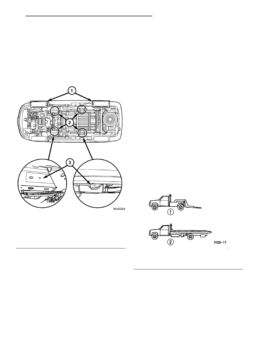
When servicing the leaf springs or the leaf spring

mounting brackets, special provisions are required to
support the rear of the vehicle. Position the rear
hoist pads under the horizontal surface on the bot-
tom of the sill, inboard adjacent to the flange and
centered fore/aft between the jacking indicator tabs
on the lower flange. DO NOT HOIST ON THE
FLANGE. 
Place a soft pad between the hoist and the
painted surface on the sill to avoid scratching the fin-
ish.

TOWING

STANDARD PROCEDURE - TOWING

WARNINGS AND CAUTIONS

WARNING: DO NOT ALLOW TOWING ATTACHMENT
DEVICES TO CONTACT THE FUEL TANK OR LINES,
FUEL LEAK CAN RESULT.
DO NOT LIFT OR TOW VEHICLE BY FRONT OR
REAR BUMPER.
DO NOT GO UNDER A LIFTED VEHICLE IF NOT
SUPPORTED PROPERLY ON SAFETY STANDS.
DO NOT ALLOW PASSENGERS TO RIDE IN A

TOWED VEHICLE.
USE A SAFETY CHAIN THAT IS INDEPENDENT
FROM THE TOWING ATTACHMENT DEVICE.

CAUTION: Do not damage brake lines, exhaust sys-
tem, shock absorbers, sway bars, or any other
under vehicle components when attaching towing
device to vehicle.
Do not secure vehicle to towing device by the use
of front or rear suspension or steering components.
Remove or secure loose or protruding objects from
a damaged vehicle before towing.
Refer to state and local rules and regulations before
towing a vehicle.
Do not allow weight of towed vehicle to bear on
lower fascia, air dams, or spoilers.

RECOMMENDED TOWING EQUIPMENT

To avoid damage to bumper fascia and air dams

use:

• FWD vehicles, use of a flat bed towing device or

a wheel lift is recommended (Fig. 8).

• AWD vehicles, a flat bed towing device or a

wheel lift and towing dolly is recommended (Fig. 8).

When using a wheel lift towing device, be sure the

disabled vehicle has at least 100 mm (4 in.) ground
clearance. If minimum ground clearance cannot be
reached, use a towing dolly. If a flat bed device is
used, the approach angle should not exceed 15
degrees.

GROUND CLEARANCE

CAUTION: If vehicle is towed with wheels removed,
install lug nuts to retain brake drums or rotors.

A towed vehicle should be raised until the lifted

wheels are a minimum 100 mm (4 in.) from the
ground. Be sure there is at least 100 mm (4 in.)
clearance between the tail pipe and the ground. If
necessary, remove the wheels from the front end of

Fig. 7 HOISTING AND JACKING POINTS

1- DRIVE ON LIFT
2 - FRAME CONTACT LIFT (SINGLE POST)
2 - CHASSIS LIFT (NON-AXLE DUAL POST)
2 - OUTBOARD LIFT (DUAL POST)
2 - FLOOR JACK
3 - S.A.E. HOISTING SYMBOLS

Fig. 8 RECOMMENDED TOWING

1 - WHEEL LIFT
2 - FLAT BED

RS

LUBRICATION & MAINTENANCE

0 - 29

HOISTING (Continued)

the vehicle and lower the front end closer to the
ground, to increase the ground clearance at the rear
of the vehicle. Install lug nuts on wheel attaching
studs to retain brake drums or rotors.

LOCKED VEHICLE TOWING

When a locked vehicle must be towed with the

front wheels on the ground, use a towing dolly or flat
bed hauler.

FLAT TOWING WITH TOW BAR

• Three speed automatic transaxle vehicles can be

flat towed at speeds not to exceed 40 km/h (25 mph)
for not more than 25 km (15 miles). The steering col-
umn must be unlocked and gear selector in neutral.

• Four speed electronic automatic transaxle vehi-

cles can be flat towed at speeds not to exceed 72
km/h (44 mph) for not more than 160 km (100 miles).
The steering column must be unlocked and gear
selector in neutral.

• AWD models should not be flat towed. For addi-

tional information, refer to RECOMMENDED TOW-
ING EQUIPMENT 
in this section.

FLAT BED TOWING TIE DOWNS

CAUTION: Do not tie vehicle down by attaching
chains or cables to suspension components or
engine mounts, damage to vehicle can result.

The vehicle can be tied to a flat bed device using

the two pair of front slots on the bottom surface of
the rails, behind the front wheels. The two pair of
rear slots on the bottom of the rail between the

bumper extension bolts and on the bottom of the rail
just

rearward

of

the

jounce

bumper.

Vehicles

equipped with a rear sway bar have brackets at this
location.

TOWING – FRONT WHEEL LIFT

If the vehicle is being towed from the front, when-

ever possible ensure at least 10 inches road clearance
to the tires.

TOWING – REAR WHEEL LIFT

If a vehicle cannot be towed with the front wheels

lifted, the rear wheels can be lifted provided the fol-
lowing guide lines are observed.

CAUTION: Do not use steering column lock to
secure steering wheel during towing operation.

• On AWD vehicles, all four wheels must be free to

rotate. Use towing dollies at unlifted end of vehicle.

• Unlock steering column and secure steering

wheel in straight ahead position with a clamp device
designed for towing.

• Three speed automatic transaxle vehicles can be

flat towed at speeds not to exceed 40 km/h (25 mph)
for not more than 25 km (15 miles). The steering col-
umn must be unlocked and gear selector in neutral.

• Four speed electronic automatic transaxle vehi-

cles can be flat towed at speeds not to exceed 72
km/h (44 mph) for not more than 160 km (100 miles).
The steering column must be unlocked and gear
selector in neutral.

0 - 30

LUBRICATION & MAINTENANCE

RS

TOWING (Continued)

SUSPENSION

TABLE OF CONTENTS

page

page

FRONT SUSPENSION

. . . . . . . . . . . . . . . . . . . . . 1

REAR SUSPENSION

. . . . . . . . . . . . . . . . . . . . . . 26

WHEEL ALIGNMENT

. . . . . . . . . . . . . . . . . . . . . 47

FRONT SUSPENSION

TABLE OF CONTENTS

page

page

FRONT SUSPENSION

DESCRIPTION - FRONT SUSPENSION

. . . . . . . 2

OPERATION - FRONT SUSPENSION

. . . . . . . . . 2

STANDARD PROCEDURE - LUBRICATION

. . . . 2

SPECIFICATIONS

FRONT SUSPENSION FASTENER TORQUE

. . 3

SPECIAL TOOLS

FRONT SUSPENSION

. . . . . . . . . . . . . . . . . . . 3

BUSHINGS

REMOVAL - STABILIZER BAR CUSHION

. . . . . . 4

INSTALLATION - STABILIZER BAR CUSHION

. . . 4

HUB / BEARING

DESCRIPTION

. . . . . . . . . . . . . . . . . . . . . . . . . . 5

OPERATION

. . . . . . . . . . . . . . . . . . . . . . . . . . . . 5

DIAGNOSIS AND TESTING - HUB AND

BEARING

. . . . . . . . . . . . . . . . . . . . . . . . . . . . 5

REMOVAL

. . . . . . . . . . . . . . . . . . . . . . . . . . . . . 5

INSTALLATION

. . . . . . . . . . . . . . . . . . . . . . . . . . 5

KNUCKLE

DESCRIPTION

. . . . . . . . . . . . . . . . . . . . . . . . . . 6

OPERATION

. . . . . . . . . . . . . . . . . . . . . . . . . . . . 7

REMOVAL - STEERING KNUCKLE

. . . . . . . . . . . 7

INSPECTION - STEERING KNUCKLE

. . . . . . . . . 9

INSTALLATION - STEERING KNUCKLE

. . . . . . . 9

LOWER BALL JOINT

DESCRIPTION

. . . . . . . . . . . . . . . . . . . . . . . . . 10

OPERATION

. . . . . . . . . . . . . . . . . . . . . . . . . . . 10

DIAGNOSIS AND TESTING - LOWER BALL

JOINT

. . . . . . . . . . . . . . . . . . . . . . . . . . . . . . 10

LOWER BALL JOINT SEAL BOOT

DESCRIPTION - EXPORT

. . . . . . . . . . . . . . . . . 10

REMOVAL

REMOVAL

. . . . . . . . . . . . . . . . . . . . . . . . . . . 11

REMOVAL - EXPORT

. . . . . . . . . . . . . . . . . . . 11

INSTALLATION

INSTALLATION

. . . . . . . . . . . . . . . . . . . . . . . 11

INSTALLATION - EXPORT

. . . . . . . . . . . . . . . 11

LOWER CONTROL ARM

DESCRIPTION

. . . . . . . . . . . . . . . . . . . . . . . . . 12

OPERATION

. . . . . . . . . . . . . . . . . . . . . . . . . . . 12

REMOVAL - LOWER CONTROL ARM

. . . . . . . . 12

DISASSEMBLY

DISASSEMBLY - LOWER CONTROL ARM

(REAR BUSHING - STANDARD) . . . . . . . . . . 13

DISASSEMBLY - LOWER CONTROL ARM

(REAR BUSHING - HYDRO) . . . . . . . . . . . . . 13

INSPECTION - LOWER CONTROL ARM

. . . . . . 14

ASSEMBLY

ASSEMBLY - LOWER CONTROL ARM

(REAR BUSHING - STANDARD) . . . . . . . . . . 14

ASSEMBLY - LOWER CONTROL ARM

(REAR BUSHING - HYDRO) . . . . . . . . . . . . . 15

INSTALLATION - LOWER CONTROL ARM

. . . . 15

STABILIZER BAR

DESCRIPTION

. . . . . . . . . . . . . . . . . . . . . . . . . 16

OPERATION

. . . . . . . . . . . . . . . . . . . . . . . . . . . 16

REMOVAL

. . . . . . . . . . . . . . . . . . . . . . . . . . . . . 17

INSPECTION

. . . . . . . . . . . . . . . . . . . . . . . . . . 17

INSTALLATION

. . . . . . . . . . . . . . . . . . . . . . . . . 17

STRUT

DESCRIPTION - STRUT ASSEMBLY

. . . . . . . . . 19

OPERATION - STRUT ASSEMBLY

. . . . . . . . . . 19

DIAGNOSIS AND TESTING - STRUT

ASSEMBLY

. . . . . . . . . . . . . . . . . . . . . . . . . . 20

REMOVAL - STRUT ASSEMBLY

. . . . . . . . . . . . 20

DISASSEMBLY - STRUT ASSEMBLY

. . . . . . . . 21

ASSEMBLY - STRUT ASSEMBLY

. . . . . . . . . . . 23

INSTALLATION - STRUT ASSEMBLY

. . . . . . . . 25

RS

SUSPENSION

2 - 1

FRONT SUSPENSION

DESCRIPTION - FRONT SUSPENSION

This vehicle has a MacPherson Strut type front

suspension (Fig. 1).

OPERATION - FRONT SUSPENSION

The front suspension allows each wheel on a vehi-

cle to adapt to different road surfaces and conditions
without greatly affecting the opposite wheel and the
ability to control the vehicle. Each side of the front
suspension is allowed to pivot so the vehicle can be
steered in the direction preferred.

A strut assembly is used in place of the front sus-

pension upper control arm and upper ball joint.
When a vehicle strikes a bump, the force is trans-
ferred through the hub, bearing, and knuckle, into
the strut assembly to absorb the force and dampen it.
The top of the strut is mounted directly to the strut
tower of the vehicle. During steering maneuvers, the
strut assembly (through a pivot bearing in the upper

strut mount) and steering knuckle (through the lower
ball joint) turn as an assembly.

STANDARD PROCEDURE - LUBRICATION

There are no serviceable lubrication points on the

front suspension. The ball joints are sealed-for-life
and require no maintenance. The lower ball joints
have special grease fitting caps that prevent normal
grease gun attachment. This has been done to elimi-
nate the possibility of over-filling, damaging the non-
vented seal. Do not attempt to remove the special
grease fitting cap and replace it with a normal grease
zirc fitting.

CAUTION: No attempt should be made to replace
the ball joint grease fitting cap with a normal zirc
fitting or fill the ball joint with grease. Damage to
the grease seal can result.

Fig. 1 Front Suspension

1 - TOWER
2 - CROSSMEMBER TAPPING PLATES
3 - LEFT STRUT ASSEMBLY
4 - LEFT STEERING KNUCKLE (WITH HUB AND BEARING)
5 - STABILIZER BAR LINK
6 - STABILIZER BAR
7 - LEFT LOWER CONTROL ARM
8 - CRADLE/CROSSMEMBER

9 - CRADLE/CROSSMEMBER REINFORCEMENT
10 - BALL JOINT
11 - ISOLATOR BUSHING
12 - STEERING GEAR TIE ROD
13 - RIGHT STEERING KNUCKLE
14 - RIGHT HUB AND BEARING
15 - RIGHT STRUT ASSEMBLY

2 - 2

FRONT SUSPENSION

RS


Content   ..  627  628  629  630   ..