Chrysler RG Voyager. Manual - part 519


  Index      Chrysler     Chrysler RG Voyager - service repair manual 2005 year


Search            


Content   ..  517  518  519  520   ..


Chrysler RG Voyager. Manual - part 519


DISASSEMBLY

NOTE: When servicing the input shaft assembly, all
snap rings which are removed MUST be replaced
with new snap rings upon reassembly. The 5th gear
nut must be replaced also.

(1) Invert input shaft assembly and place in fix-

ture 8487.

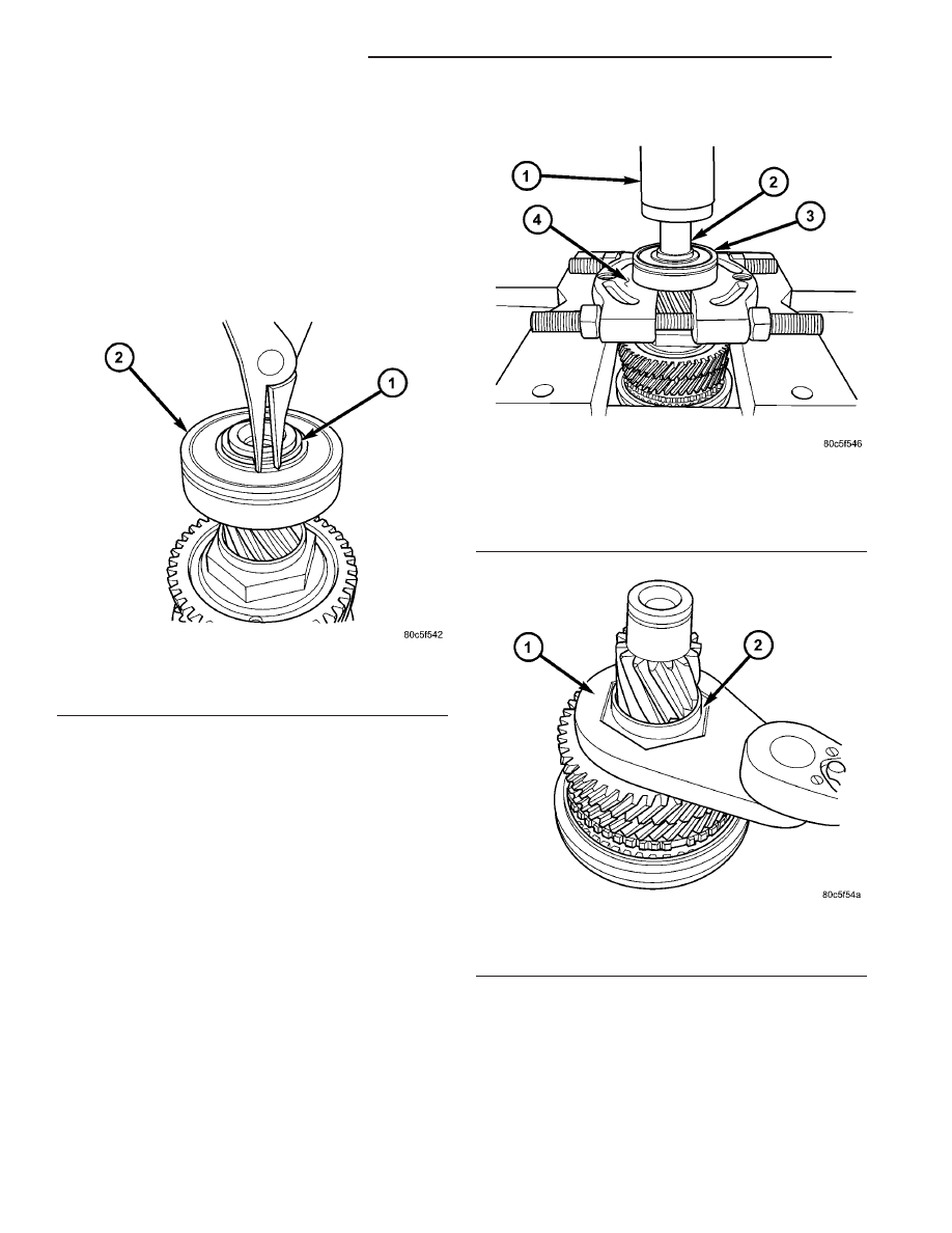
(2) Remove input bearing snap ring (Fig. 216).

(3) Remove

input

bearing.

Place

input

shaft

assembly onto arbor press table, with the input bear-
ing supported by bearing splitter (Fig. 217). Using
adapter 8486-4, press bearing off of shaft, while
helper supports shaft to prevent dropping.

(4) Place input shaft assembly back into fixture

8487. Secure fixture to bench with fasteners, or
secure to bench vise.

NOTE: 5th gear nut is staked to the shaft. If neces-
sary, grind stake area to ease removal, but use care
not to contact gear.

(5) Remove 5th gear nut with wrench 8478 (Fig.

218). Discard nut and use a new one upon assembly.

(6) Remove 5th gear with arbor press and bearing

splitter.

Fig. 216 Input Bearing Snap Ring Removal

1 - SNAP RING
2 - INPUT BEARING

Fig. 217 Input Bearing Removal

1 - ARBOR PRESS RAM
2 - ADAPTER 8486-4
3 - INPUT BEARING
4 - BEARING SPLITTER

Fig. 218 5th Gear Nut Removal/Installation

1 - WRENCH 8478
2 - 5TH GEAR NUT

21a - 98

T850 MANUAL TRANSAXLE

RG

INPUT SHAFT (Continued)

(7) Remove 4th gear and needle bearing (Fig. 219)

(Fig. 220).

(8) Remove 4th gear blocker ring (Fig. 221).

(9) Remove 3/4 synchronizer snap ring (Fig. 222).

Discard and replace with new snap ring upon assem-
bly.

Fig. 219 4th Gear Removal/Installation

1 - 4TH GEAR
2 - NEEDLE BEARING

Fig. 220 4th Gear Needle Bearing Removal/

Installation

1 - 4TH GEAR NEEDLE BEARING

Fig. 221 4th Gear Blocker Ring

1 - 4th GEAR BLOCKER RING

Fig. 222 3/4 Synchro Snap Ring

1 - SNAP RING
2 - 3/4 SYNCHRONIZER

RG

T850 MANUAL TRANSAXLE

21a - 99

INPUT SHAFT (Continued)

(10) Remove 3/4 synchronizer (Fig. 223).

(11) Remove 3rd gear blocker ring (Fig. 224).

(12) Remove 3rd gear and needle bearing (Fig.

225) (Fig. 226).

(13) Inspect third gear thrust washer for signs of

excessive wear. To replace, drive off of input shaft
with suitable drift and hammer.

Fig. 223 3/4 Synchro Assembly

1 - 3/4 SYNCHRONIZER

Fig. 224 3rd Gear Blocker Ring

1 - 3RD GEAR BLOCKER RING

Fig. 225 3rd Gear Removal/Installation

1 - 3RD GEAR
2 - NEEDLE BEARING

Fig. 226 3rd Gear Needle Bearing Removal/

Installation

1 - 3RD GEAR NEEDLE BEARING
2 - THRUST WASHER

21a - 100

T850 MANUAL TRANSAXLE

RG

INPUT SHAFT (Continued)

ASSEMBLY

NOTE: When servicing the input shaft assembly, all
snap rings MUST be replaced with new ones upon
assembly. 5th gear nut must also be replaced.

NOTE: When installing 3/4 synchronizer hub to
shaft, make sure to align oil slots on synchronizer
hub face with oil hole in the shaft splined hub jour-
nal.

NOTE: Refer to (Fig. 227) for input shaft assembly
reference.

(1) Install input shaft into fixture 8487.
(2) Install thrust washer if removed upon disas-

sembly.

(3) Install 3rd gear and needle bearing (Fig. 228)

(Fig. 229).

Fig. 227 Input Shaft Assembly

1 - INPUT SHAFT

7 - SNAP RING

2 - THRUST WASHER

8 - INPUT BEARING (SEALED)

3 - 3RD GEAR

9 - NEEDLE BEARING

4 - 4TH GEAR

10 - SNAP RING

5 - 5TH GEAR

11 - 3/4 SYNCHRONIZER

6 - 5TH GEAR NUT

12 - NEEDLE BEARING

Fig. 228 3rd Gear Needle Bearing Removal/Installation

1 - 3RD GEAR NEEDLE BEARING
2 - THRUST WASHER

RG

T850 MANUAL TRANSAXLE

21a - 101

INPUT SHAFT (Continued)


Content   ..  517  518  519  520   ..