Chrysler RG Voyager. Manual - part 475


  Index      Chrysler     Chrysler RG Voyager - service repair manual 2005 year


Search            


Content   ..  473  474  475  476   ..


Chrysler RG Voyager. Manual - part 475


(8) Install timing belt (Refer to 9 - ENGINE/

VALVE

TIMING/TIMING

BELT/CHAIN

AND

SPROCKETS - INSTALLATION).

(9) Install timing belt outer cover (Refer to 9 -

ENGINE/VALVE TIMING/TIMING BELT / CHAIN
COVER(S) - INSTALLATION).

(10) Install right engine mount (Refer to 9 -

ENGINE/ENGINE MOUNTING/RIGHT MOUNT -
INSTALLATION).

(11) Install generator (Refer to 8 - ELECTRICAL/

CHARGING/GENERATOR - INSTALLATION).

(12) Install accessory drive belt (Refer to 7 -

COOLING/ACCESSORY

DRIVE/DRIVE

BELTS

-

INSTALLATION).

(13) Install power steering belt (Refer to 7 -

COOLING/ACCESSORY

DRIVE/DRIVE

BELTS

-

INSTALLATION).

(14) Install air cleaner housing.
(15) Refill cooling system (Refer to 7 - COOLING/

ENGINE/COOLANT - STANDARD PROCEDURE).

(16) Install front wiper unit (Refer to 8 - ELEC-

TRICAL/WIPERS/WASHERS/WIPER

MODULE

-

INSTALLATION).

(17) Connect negative battery cable.

CYLINDER HEAD COVER(S)

DESCRIPTION

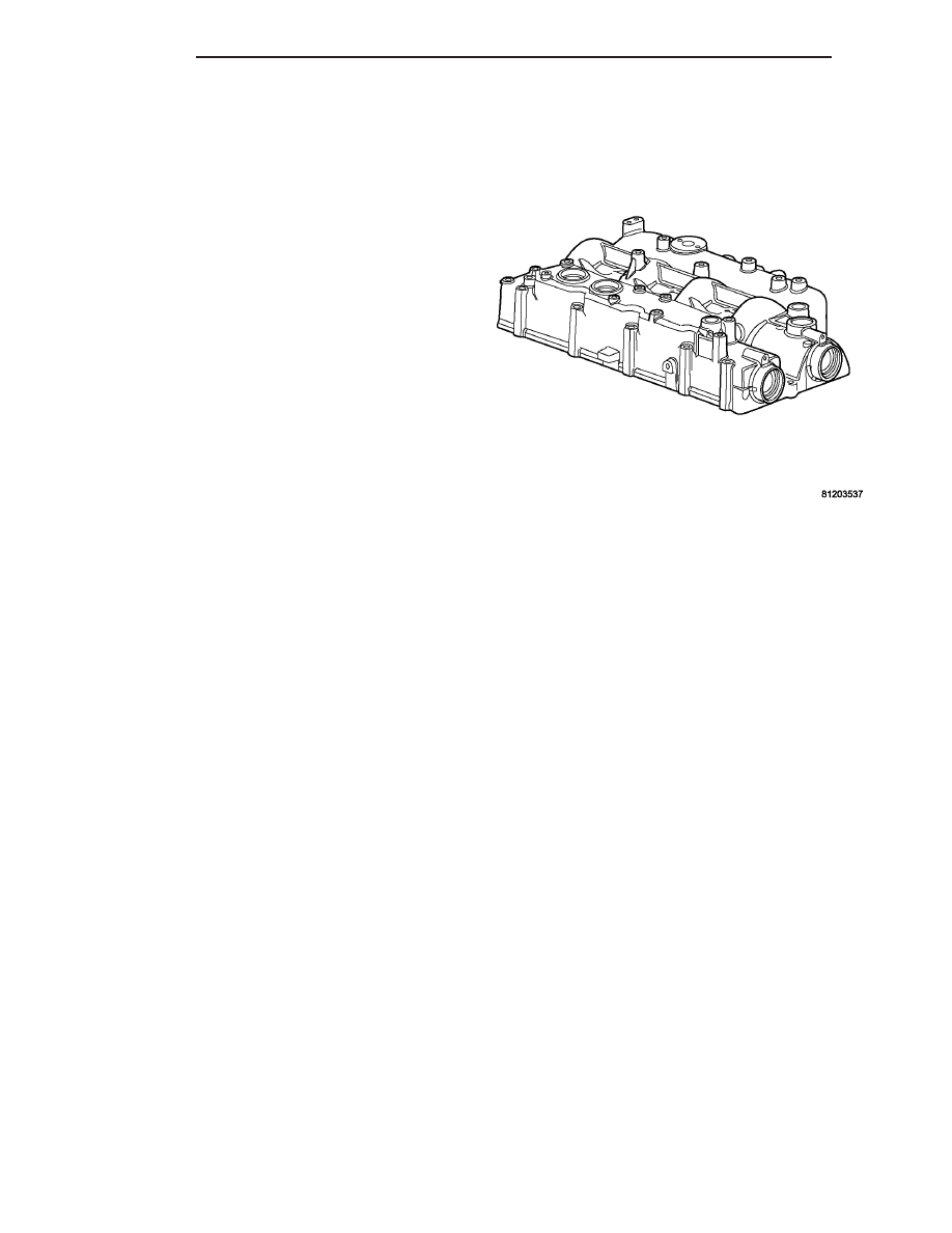
The cylinder head cover is made of cast aluminum

and is also the intake manifold on this engine. The cyl-
inder head cover is equipped with a double breather
port and an internal oil return pipe (Fig. 24).

REMOVAL

REMOVAL

CAUTION: Before removing the cylinder head cover/
intake manifold the engine must put at 90° after
TDC. Failure to do so could result in valve and/or
piston damage during reassembly. (Refer to 9 -
ENGINE/VALVE TIMING - STANDARD PROCEDURE)

(1) Disconnect negative battery cable.
(2) Remove front wiper unit (Refer to 8 - ELEC-

TRICAL/WIPERS/WASHERS/WIPER

MODULE

-

REMOVAL).

(3) Remove engine cover (Refer to 9 - ENGINE -

REMOVAL).

(4) Drain cooling system (Refer to 7 - COOLING/

ENGINE/COOLANT - STANDARD PROCEDURE).

(5) Rotate engine until 90° after TDC is reached.

Install both camshaft locking pins and the crankshaft
locking pin. (Refer to 9 - ENGINE/VALVE TIMING -
STANDARD PROCEDURE)

(6) Remove air cleaner housing assembly.
(7) Remove power steering belt (Refer to 7 -

COOLING/ACCESSORY

DRIVE/DRIVE

BELTS

-

REMOVAL).

(8) Remove accessory drive belt (Refer to 7 -

COOLING/ACCESSORY

DRIVE/DRIVE

BELTS

-

REMOVAL).

(9) Remove generator (Refer to 8 - ELECTRICAL/

CHARGING/GENERATOR - REMOVAL).

(10) Support engine and remove right engine

mount (Refer to 9 - ENGINE/ENGINE MOUNTING/
RIGHT MOUNT - REMOVAL).

(11) Remove outer timing belt cover (Refer to 9 -

ENGINE/VALVE TIMING/TIMING BELT / CHAIN
COVER(S) - REMOVAL).

(12) Remove timing belt (Refer to 9 - ENGINE/

VALVE

TIMING/TIMING

BELT/CHAIN

AND

SPROCKETS - REMOVAL).

(13) Remove inner timing belt cover (Refer to 9 -

ENGINE/VALVE TIMING/TIMING BELT / CHAIN
COVER(S) - REMOVAL).

(14) Disconnect camshaft position sensor, boost

pressure/intake air temperature sensor, EGR sole-
noid, and fuel pressure sensor electrical connectors
(Fig. 25).

(15) Disconnect vacuum lines at EGR solenoid.
(16) Position electrical harness out of way.
(17) Remove fuel injectors (Refer to 14 - FUEL

SYSTEM/FUEL

INJECTION/FUEL

INJECTOR

-

REMOVAL).

(18) Remove fuel rail (Refer to 14 - FUEL SYS-

TEM/FUEL DELIVERY/FUEL RAIL - REMOVAL).

Fig. 24 CYLINDER HEAD COVER/INTAKE

MANIFOLD

9 - 32

ENGINE

RG

CAMSHAFT(S) (Continued)

(19) Remove power steering pump reservoir from

bracket.

(20) Remove oil dipstick tube retaining bolt at

intake manifold inlet.

(21) Disconnect oil separator outlet hose at separa-

tor.

(22) Remove turbo inlet tube retaining bolt at

intake manifold.

(23) Disconnect EGR tube at intake manifold inlet

tube.

(24) Remove cylinder head cover/intake manifold

retaining bolts (Fig. 26).

(25) Lift cylinder head cover/intake manifold from

cylinder head (Fig. 26).

NOTE: While cleaning the oil return passage in the
cylinder head cover, be sure to clean the drain back
tube in the cylinder head as well.

(26) Clean the oil return hole in the oil separator

access hole with compressed air (Fig. 27).

Fig. 25 ENGINE COMPONENT LOCATIONS

1 - FUEL INJECTOR RETURN LINE
2 - FUEL INJECTOR SUPPLY LINE
3 - OIL SEPARATOR
4 - FUEL INJECTOR
5 - CAMSHAFT POSITION SENSOR
6 - BOOST PRESSURE/INTAKE AIR TEMPERATURE SENSOR
7 - EGR SOLENOID
8 - FUEL PRESSURE SENSOR
9 - CYLINDER HEAD COVER/INTAKE MANIFOL
10 - FUEL RAIL
11 - WIRING HARNESS RETAINING CLIPS

Fig. 26 CYLINDER HEAD COVER/INTAKE

MANIFOLD ASSEMBLY

1 - CYLINDER HEAD COVER/INTAKE MANIFOLD BOLTS(LONG)
2 - CYLINDER HEAD COVER/INTAKE MANIFOLD
3 - CYLINDER HEAD
4 - CYLINDER HEAD COVER/INTAKE MANIFOLD GASKET
5 - CYLINDER HEAD COVER/INTAKE MANIFOLD BOLTS(SHORT)

Fig. 27 OIL RETURN PASSAGE

1 - CYLINDER HEAD COVER/INTAKE MANIFOLD
2 - OIL RETURN PASSAGE

RG

ENGINE

9 - 33

CYLINDER HEAD COVER(S) (Continued)

NOTE: When removing rocker arm and lifter assem-
blies, be sure to keep them in order as they were
removed from the cylinder head. Always keep lifters
in an upright position when removed from cylinder
head.

(27) Remove rocker arm and lifter assemblies from

cylinder head (Fig. 28).

(28) Remove cylinder head cover/intake manifold

gasket from cylinder head.

REMOVAL

(1) Disconnect the negative battery cable.
(2) Remove the engine cover (Refer to 9 - ENGINE

- REMOVAL).

(3) Remove the engine oil separator fastener and

remove the separator (Fig. 29).

(4) Using compressed air, blow out the oil drain

back passage in the cylinder head cover/intake man-
ifold assembly.

NOTE: If the cylinder head cover/intake manifold is
removed, be sure to clean the oil drain back tube as
well.

INSTALLATION

INSTALLATION

(1) Clean and inspect sealing surfaces.
(2) Clean and inspect the breather oil return pas-

sage in the cylinder head/intake manifold cover (Fig.
27).

(3) Install new gasket on cylinder head.

NOTE: Apply a small amount of grease on each
valve stem. This will help hold the rocker arm in
position during the cylinder head cover installation.

(4) Install rocker arm and lifter assemblies in cyl-

inder head (Fig. 28).Be sure to put rocker arm
and

lifter

assemblies

in

same

location

as

removed.

(5) Install cylinder head cover/intake manifold

alignment studs in cylinder head (Fig. 30).

(6) Install cylinder head cover/intake manifold

over alignment stud.

NOTE: Be sure to lubricate cylinder head cover/in-
take manifold retaining bolts with engine oil before
assembly. If new bolts are being installed, DO NOT
lubricate before assembly.

(7) Install two cylinder head cover/intake manifold

retaining bolts and tighten finger tight.

Fig. 28 CYLINDER HEAD COVER/INTAKE

MANIFOLD GASKET LOCATION

1 - THERMOSTAT HOUSING
2 - ROCKER ARM AND LIFTER ASSEMBLY
3 - CYLINDER HEAD COVER/INTAKE MANIFOLD
4 - CYLINDER HEAD

Fig. 29 ENGINE OIL SEPARATOR

1 - SCREW
2 - ENGINE OIL SEPARATOR
3 - O-RINGS

9 - 34

ENGINE

RG

CYLINDER HEAD COVER(S) (Continued)

(8) Remove alignment studs and install remaining

retaining bolts (Fig. 26). Tighten retaining bolts fin-
ger tight.

(9) Torque cylinder head cover/intake manifold

retaining bolts following procedure below.

CYLINDER HEAD COVER/INTAKE MANIFOLD
TIGHTENING PROCEDURE

• Coat all bolts being reused with clean engine oil.

• Install the M8x35 bolts into holes 1,2,3,4,5, and

12.

Install

the

M8x85

bolts

into

holes

6,7,8,9,10,11,13,14,15, and 16. Tighten all bolt hand
tight
.

• Alternate between bolts #11 and #16 to seat cyl-

inder head cover/intake manifold on cylinder head
(Fig. 31). Torque bolts to 7 N·m.

• Torque all cylinder head cover/intake manifold

retaining bolts to 25 N·m in numerical order starting
with #1 and ending with #16 (Fig. 31).

(10) Connect EGR tube at intake manifold inlet

tube. Torque clamp to 10.8 N·m.

(11) Install turbo inlet tube retaining bolt at

intake manifold. Torque bolt to 27.5 N·m.

(12) Connect oil separator outlet hose at separator.
(13) Install oil dipstick tube retaining bolt at

intake manifold inlet. Torque bolt to 10 N·m.

(14) Install power steering pump reservoir in

bracket.

(15) Install fuel rail (Refer to 14 - FUEL SYSTEM/

FUEL DELIVERY/FUEL RAIL - INSTALLATION).

(16) Install fuel injectors and fuel injector supply

lines (Refer to 14 - FUEL SYSTEM/FUEL INJEC-
TION/FUEL INJECTOR - INSTALLATION).

(17) Connect vacuum lines at EGR solenoid.
(18) Clip wiring harness retainers on studs on fuel

rail (Fig. 25).

(19) Connect camshaft position sensor, boost pres-

sure/intake air temperature sensor, EGR solenoid,
and fuel pressure sensor electrical connectors (Fig.
25).

(20) Install inner timing belt cover (Refer to 9 -

ENGINE/VALVE TIMING/TIMING BELT / CHAIN
COVER(S) - INSTALLATION).

(21) Install timing belt (Refer to 9 - ENGINE/

VALVE

TIMING/TIMING

BELT/CHAIN

AND

SPROCKETS - INSTALLATION).

(22) Install outer timing belt cover (Refer to 9 -

ENGINE/VALVE TIMING/TIMING BELT / CHAIN
COVER(S) - INSTALLATION).

(23) Install right engine mount (Refer to 9 -

ENGINE/ENGINE MOUNTING/RIGHT MOUNT -
INSTALLATION).

(24) Install generator (Refer to 8 - ELECTRICAL/

CHARGING/GENERATOR - INSTALLATION).

(25) Install accessory drive belt (Refer to 7 -

COOLING/ACCESSORY

DRIVE/DRIVE

BELTS

-

INSTALLATION).

(26) Install power steering belt (Refer to 7 -

COOLING/ACCESSORY

DRIVE/DRIVE

BELTS

-

INSTALLATION).

Fig. 30 CYLINDER HEAD COVER/INTAKE

MANIFOLD ALIGNMENT STUDS VM.1066

1 - CYLINDER HEAD COVER/INTAKE MANIFOLD ALIGNMENT
STUDS VM.1066
2 - CYLINDER HEAD

Fig. 31 CYLINDER HEAD COVER/INTAKE

MANIFOLD TIGHTENING SEQUENCE

RG

ENGINE

9 - 35

CYLINDER HEAD COVER(S) (Continued)


Content   ..  473  474  475  476   ..