Chrysler RG Voyager. Manual - part 462


  Index      Chrysler     Chrysler RG Voyager - service repair manual 2005 year


Search            


Content   ..  460  461  462  463   ..


Chrysler RG Voyager. Manual - part 462


COOLING SYSTEM DRAINING

WARNING: DO NOT REMOVE OR LOOSEN THE
COOLANT

PRESSURE/VENT

CAP,

CYLINDER

BLOCK DRAIN PLUGS, OR THE DRAINCOCK WHEN
THE SYSTEM IS HOT AND UNDER PRESSURE
BECAUSE SERIOUS BURNS FROM THE COOLANT
CAN OCCUR.

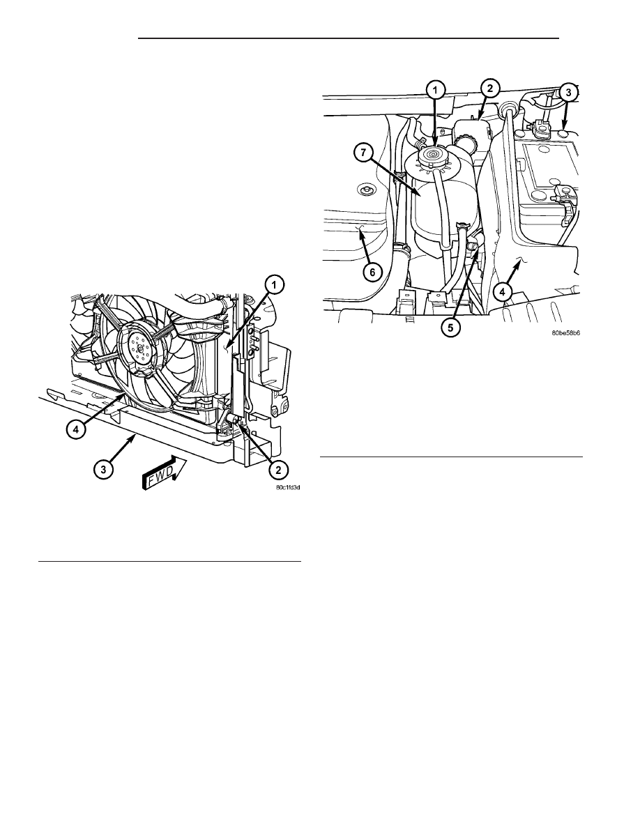
(1) Without removing pressure/vent cap and

with system not under pressure, open the drain-
cock. The draincock is located on the lower right side
of radiator (Fig. 3).

(2) After the coolant recovery pressure container is

empty, then remove coolant pressure/vent cap.

COOLANT RECOVERY PRESS
CONTAINER

DESCRIPTION

The

coolant

recovery

pressure

container

is

mounted in the engine compartment next to the bat-
tery. The coolant recovery pressure container is made
of plastic (Fig. 4).

OPERATION

The coolant recovery pressure container works

with the pressure/vent cap to use thermal expansion
and contraction of the coolant to keep the coolant
free of trapped air. Provides a convenient and safe
method for checking coolant level and adjusting level
at atmospheric pressure without removing the pres-
sure/vent cap. It also provides some reserve coolant
to cover deaeration, evaporation, or boiling losses.

REMOVAL

(1) Drain cooling system below level of coolant

recovery pressure bottle. (Refer to 7 - COOLING/EN-
GINE/COOLANT - STANDARD PROCEDURE)

(2) Disconnect coolant bypass and overflow hoses

from coolant recovery pressure container (Fig. 6).

Fig. 3 DRAINCOCK LOCATION

1 - RADIATOR
2 - DRAINCOCK
3 - LOWER RADIATOR SUPPORT
4 - ELECTRIC COOLING FAN

Fig. 4 COOLANT RECOVERY PRESSURE

CONTAINER LOCATION

1 - PRESSURE/VENT CAP
2 - BRAKE MASTER CYLINDER
3 - BATTERY
4 - BATTERY SHIELD
5 - COOLANT RECOVERY PRESSURE CONTAINER RETAING
CLIP
6 - ENGINE COVER
7 - COOLANT RECOVERY PRESSURE CONTAINER

7a - 16

ENGINE

RG

COOLANT (Continued)

(3) Unclip the coolant recovery pressure container

retaining clip (Fig. 5).

(4) Raise coolant recovery pressure container from

mounting bracket and disconnect coolant hose from
bottom of container (Fig. 6).

(5) Remove coolant recovery pressure bottle.

INSTALLATION

(1) Connect coolant hose at bottom of coolant

recovery pressure container (Fig. 6) and install in
mounting bracket.

(2) Connect coolant recovery pressure container

retaining clip (Fig. 5).

(3) Connect coolant bypass and overflow hoses to

coolant recovery pressure container.

(4) Refill cooling system. (Refer to 7 - COOLING/

ENGINE/COOLANT - STANDARD PROCEDURE)

ENGINE COOLANT TEMP
SENSOR

DESCRIPTION

The engine coolant temperature sensor threads

into a coolant passage in the cylinder head (Fig. 7).
New sensors have sealant applied to the threads.

OPERATION

The coolant temperature (ECT) sensor is a nega-

tive temperature coefficient (NTC) thermistor (resis-
tance varies inversely with temperature). This means
at cold temperatures its resistance is high so the
voltage signal will be high. As coolant temperature
increases, resistance decreases and the signal voltage
will be low. This allows the sensor to provide an ana-
log voltage signal to the ECM.

Fig. 5 COOLANT RECOVERY PRESSURE

CONTAINER LOCATION

1 - PRESSURE/VENT CAP
2 - BRAKE MASTER CYLINDER
3 - BATTERY
4 - BATTERY SHIELD
5 - COOLANT RECOVERY PRESSURE CONTAINER RETAING
CLIP
6 - ENGINE COVER
7 - COOLANT RECOVERY PRESSURE CONTAINER

Fig. 6 COOLANT RECOVERY PRESSURE

CONTAINER

1 - COOLANT RECOVERY PRESSURE CONTAINER
2 - COOLANT BYPASS HOSE
3 - OUTLET HOSE
4 - PRESSURE/VENT CAP

RG

ENGINE

7a - 17

COOLANT RECOVERY PRESS CONTAINER (Continued)

REMOVAL

WARNING: DO NOT REMOVE OR LOOSEN THE
COOLANT

PRESSURE/VENT

CAP,

CYLINDER

BLOCK DRAIN PLUGS, OR THE DRAINCOCK WHEN
THE SYSTEM IS HOT AND UNDER PRESSURE
BECAUSE SERIOUS BURNS FROM THE COOLANT
CAN OCCUR.

(1) Drain the cooling system. (Refer to 7 - COOL-

ING/ENGINE/COOLANT

-

STANDARD

PROCE-

DURE)

(2) Disconnect coolant temperature sensor electri-

cal connector (Fig. 8).

(3) Remove coolant temperature sensor from cylin-

der head (Fig. 8).

INSTALLATION

(1) Install coolant temperature sensor in cylinder

head (Fig. 8).

(2) Connect coolant temperature sensor electrical

connector (Fig. 8).

(3) Refill the cooling system. (Refer to 7 - COOL-

ING/ENGINE/COOLANT

-

STANDARD

PROCE-

DURE)

(4) Connect the negative battery cable.

ENGINE COOLANT
THERMOSTAT

DESCRIPTION

A pellet-type thermostat controls the operating

temperature of the engine by controlling the amount
of coolant flow to the radiator (Fig. 9).

OPERATION

The thermostat starts to open at 88°C (190°F).

Above this temperature, coolant is allowed to flow to
the radiator. This provides quicker engine warmup
and overall temperature control.

The same thermostat is used for winter and sum-

mer seasons. An engine should not be operated with-
out a thermostat, except for servicing or testing.
Operating without a thermostat causes other prob-
lems. These are: longer engine warmup time, unreli-
able

warmup

performance,

increased

exhaust

emissions and crankcase condensation. This conden-
sation can result in sludge formation.

Fig. 7 COOLANT TEMPERATURE SENSOR

LOCATION

1 - EGR SOLENOID
2 - UPPER RADIATOR HOSE
3 - COOLANT TEMPERATURE SENSOR
4 - INTAKE MANIFOLD INLET
5 - INTAKE MANIFOLD/CYLINDER HEAD COVER

Fig. 8 COOLANT TEMPERATURE SENSOR

LOCATION

1 - EGR SOLENOID
2 - UPPER RADIATOR HOSE
3 - COOLANT TEMPERATURE SENSOR
4 - INTAKE MANIFOLD INLET
5 - INTAKE MANIFOLD/CYLINDER HEAD COVER

7a - 18

ENGINE

RG

ENGINE COOLANT TEMP SENSOR (Continued)

REMOVAL

NOTE: The thermostat is not serviced separately.
The thermostat and housing must be replaced as
an assembly.

(1) Disconnect negative battery cable.
(2) Drain cooling system (Refer to 7 - COOLING/

ENGINE/COOLANT - STANDARD PROCEDURE).

(3) Remove front wiper unit to gain access to ther-

mostat housing(Refer to 8 - ELECTRICAL/WIPERS/
WASHERS/WIPER MODULE - REMOVAL).

(4) Disconnect upper radiator hose adapter tube,

water pump hose, and EGR hose at thermostat hous-
ing.

(5) Remove both thermostat housing attaching

bolts and housing (Fig. 10).

INSTALLATION

(1) Install thermostat housing, gasket, and retain-

ing bolts (Fig. 10). Torque bolts to 27.5N·m.

(2) Connect upper radiator hose adapter tube,

water pump hose, and EGR cooler hose to thermostat
housing.

(3) Install front wiper unit (Refer to 8 - ELECTRI-

CAL/WIPERS/WASHERS/WIPER

MODULE

-

INSTALLATION).

(4) Refill cooling system (Refer to 7 - COOLING/

ENGINE/COOLANT - STANDARD PROCEDURE).

(5) Connect negative battery cable.

RADIATOR

DESCRIPTION

The radiator is a cross-flow type (horizontal tubes)

with design features that provide greater strength
along with sufficient heat transfer capabilities to
keep the engine satisfactorily cooled. The radiator
has plastic side tanks and aluminum cooling tubes.

OPERATION

The radiator functions as a heat exchanger, using

air flow across the exterior of the radiator tubes. This
heat is then transferred from the coolant and into
the passing air.

REMOVAL

(1) Disconnect negative cable from battery.
(2) Remove radiator upper crossmember support.

(Refer to 23 - BODY/EXTERIOR/GRILLE OPENING
REINFORCEMENT - REMOVAL)

Fig. 9 THERMOSTAT HOUSING

1 - CYLINDER HEAD COVER
2 - THERMOSTAT HOUSING
3 - AIR BLEED
4 - WATER PUMP
5 - WATER PUMP HOUSING TO THERMOSTAT HOUSING
BYPASS HOSE
6 - EGR VALVE

Fig. 10 THERMOSTAT HOUSING ASSEMBLY

1 - THERMOSTAT HOUSING GASKET
2 - THERMOSTAT HOUSING
3 - RETAINING BOLTS
4 - CYLINDER HEAD
5 - CYLINDER HEAD COVER/INTAKE MANIFOLD

RG

ENGINE

7a - 19

ENGINE COOLANT THERMOSTAT (Continued)


Content   ..  460  461  462  463   ..