Chrysler RG Voyager. Manual - part 351


  Index      Chrysler     Chrysler RG Voyager - service repair manual 2005 year


Search            


Content   ..  349  350  351  352   ..


Chrysler RG Voyager. Manual - part 351


4.0

DISCLAIMERS, SAFETY,
WARNINGS

4.1

DISCLAIMERS

All information, illustrations, and specifications

contained in this manual are based on the latest
information available at the time of publication.
The right is reserved to make changes at any time
without notice.

4.2

SAFETY

4.2.1

TECHNICIAN SAFETY INFORMATION

WARNING: ENGINES PRODUCE CARBON
MONOXIDE THAT IS ODORLESS, CAUSES
SLOWER REACTION TIME, AND CAN LEAD
TO SERIOUS INJURY. WHEN THE ENGINE IS
OPERATING, KEEP SERVICE AREAS WELL
VENTILATED OR ATTACH THE VEHICLE
EXHAUST SYSTEM TO THE SHOP EXHAUST
REMOVAL SYSTEM.

Set the parking brake and block the wheels before

testing or repairing the vehicle. It is especially
important to block the wheels on front-wheel drive
vehicles; the parking brake does not hold the drive
wheels.

When servicing a vehicle, always wear eye pro-

tection, and remove any metal jewelry such as
rings, watchbands or bracelets that might make an
inadvertent electrical contact.

When diagnosing a chassis problem, it is impor-

tant to follow approved procedures where applica-
ble. These procedures can be found in the service
manual. Following these procedures is very impor-
tant to the safety of individuals performing diag-
nostic tests.

4.2.2

VEHICLE PREPARATION FOR
TESTING

Make sure the vehicle being tested has a fully

charged battery. If it does not, false diagnostic codes
or error messages may occur.

4.2.3

SERVICING SUB-ASSEMBLIES

Some components of the chassis system are in-

tended to be serviced as an assembly only. Attempt-
ing to remove or repair certain system sub-
components may result in personal injury and/or
improper system operation. Only those components
with approved repair and installation procedures in
the service manual should be serviced.

4.2.4

DRBIII

SAFETY INFORMATION

WARNING: EXCEEDING THE LIMITS OF THE
DRBIII

T

MULTIMETER IS DANGEROUS. IT

CAN

EXPOSE

YOU

TO

SERIOUS

OR

POSSIBLY

FATAL

INJURY.

CAREFULLY

READ AND UNDERSTAND THE CAUTIONS
AND THE SPECIFICATION LIMITS.

Follow the vehicle manufacturer’s service speci-
fications at all times.

Do not use the DRBIII

t if it has been damaged.

Do not use the test leads if the insulation is
damaged or if metal is exposed.

To avoid electrical shock, do not touch the test
leads, tips, or the circuit being tested.

Choose the proper range and functions for the
measurement. Do not try voltage or current mea-
surements that may exceed the rated capacity.
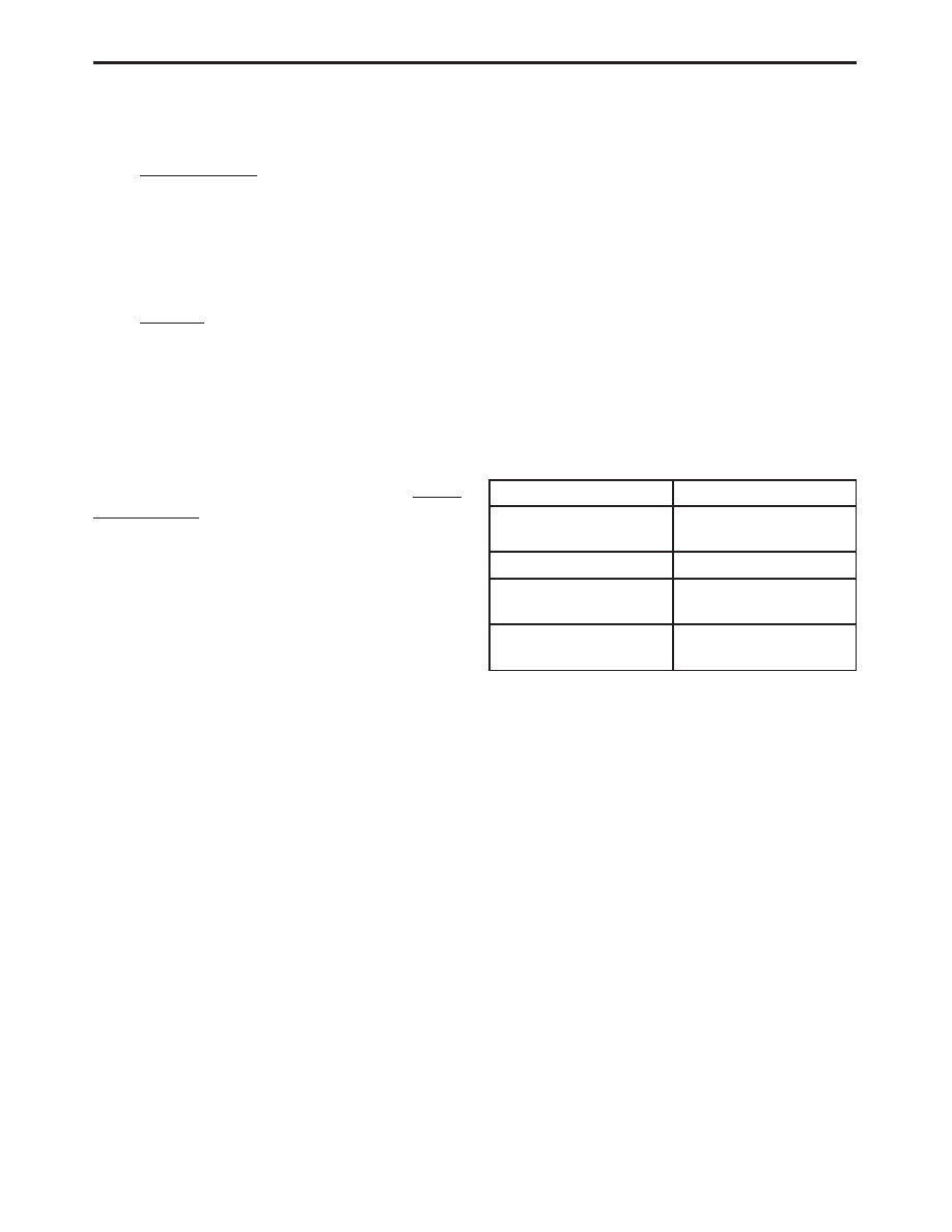
Do not exceed the limits shown in the table below:

FUNCTION

INPUT LIMIT

Volts

0 - 500 peak volts AC
0 - 500 volts DC

Ohms (resistance)*

0 -1.12 megohms

Frequency Measured
Frequency Generated

0 - 10 kHz

Temperature

-58 - 1100°F
-50 - 600°C

* Ohms cannot be measured if voltage is present.

Ohms can be measured only in a non-powered
circuit.

Voltage between any terminal and ground must
not exceed 500v DC or 500v peak AC.

Use caution when measuring voltage above 25v
DC or 25v AC.

Use the low current shunt to measure circuits up
to 10A. Use the high current clamp to measure
circuits exceeding 10A.

When testing for the presence of voltage or cur-
rent, make sure the meter is functioning cor-
rectly. Take a reading of a known voltage or
current before accepting a zero reading.

When measuring current, connect the meter in
series with the load.

Disconnect the live test lead before disconnecting
the common test lead.

When using the meter function, keep the
DRBIII

t away from spark plug or coil wires to

avoid measuring error from outside interference.

5

GENERAL INFORMATION

4.3

WARNINGS

4.3.1

VEHICLE DAMAGE WARNINGS

Before disconnecting any control module, make

sure the ignition is ‘‘off ’’. Failure to do so could
damage the module.

When testing voltage or continuity at any control

module, use the terminal side (not the wire end) of
the connector. Do not probe a wire through the
insulation, this will damage it and eventually cause
it to fail because of corrosion.

Be careful when performing electrical tests so as

to prevent accidental shorting of terminals. Such
mistakes can damage fuses or components. Also, a
second code could be set, making diagnosis of the
original problem more difficult.

4.3.2

ROAD TESTING A COMPLAINT
VEHICLE

Some complaints will require a test drive as part

of the repair verification procedure. The purpose of
the test drive is to try to duplicate the diagnostic
code or symptom condition.

WARNING:

BEFORE

ROAD

TESTING

A

VEHICLE,

BE

SURE

THAT

ALL

COMPONENTS

ARE

REASSEMBLED.

DURING THE TEST DRIVE, DO NOT TRY TO
READ THE DRB SCREEN WHILE IN MOTION.
DO NOT HANG THE DRBIII

T

FROM THE

REAR

VIEW

MIRROR

OR

OPERATE

IT

YOURSELF.

HAVE

AN

ASSISTANT

AVAILABLE TO OPERATE THE DRBIII

T

.

4.4

DIAGNOSIS

1. Your diagnostic test procedure must begin with a

thorough visual inspection of the system in ques-
tion for damaged components or disconnected
connectors. For ABS the brake lamps must be
operational prior to continuing.

2. Connect the DRBIII

t to the data link connector,

which is located under the dash to the left of the
steering column. If the DRBIII

t does not power

up, check the power and ground supplies to the
connector.

3. Turn the ignition on. Select the system in ques-

tion. If the DRBIII

t displays “No Response”

condition you must diagnose that first.

4. Read and record all diagnostic trouble codes. For

ABS if the “CAB Internal Failure” or “Battery
Voltage Out of Range” diagnostic trouble code is
present, it must be repaired prior to addressing
any other DTC’s. If any additional DTC’s are

present, proceed to the appropriate test by locat-
ing the matching test in the Table of Contents
and begin to diagnose the symptom.

5. For ABS if there are no diagnostic trouble codes

present, identify the customer complaint. Select
“Inputs/Outputs” and read the brake switch in-
put as you press and release the brake pedal. If
the display does not match the state of the pedal,
diagnose the symptom. If a problem exists with
the amber “ABS” warning indicator or the red
“Brake” indicator exists, diagnose the symptom.
Read the traction control switch input as you
press and release the switch. If the display does
not match the state of the indicator, diagnose the
symptom.

6. If no other problems are found, it will be neces-

sary to road test the vehicle. Perform several
antilock stops from above 50 Km/h (30 mph) and
then repeat step 4. If any diagnostic trouble
codes are present, proceed to the appropriate
test.

7. The following conditions should be considered

“NORMAL” operation, and no repairs should be
attempted to correct them.

– Brake pedal feedback during an ABS stop

(clicking, vibrating).

– Clicking, groaning or buzzing at 25 Km/h (15

mph) or 40 Km/h (24 mph) (drive off self test).

– Groaning noise during an ABS stop.

– Slight brake pedal drop and pop noise when

ignition is initially turned on.

– Brake pedal ratcheting down at the end of an

ABS stop.

8. If the complaint is ABS “cycling” at the end of a

stop at low speeds, it may be caused by a
marginal wheel speed sensor signal. The sensor
air gap, tone wheel condition, and/or brakes
hanging up are possible causes of this condition.

9. After a road test in which no problems were

found, refer to any Technical Service Bulletins
that may apply.

5.0

REQUIRED TOOLS AND
EQUIPMENT

DRBIII

t (diagnostic read-out box)

jumper wires
ohmmeter
voltmeter
test light

6

GENERAL INFORMATION

6.0

GLOSSARY OF TERMS

ABM

anti-lock brake module

ABS

antilock brake system

BCM

body control module

CAB

controller antilock brake

DC

direct current

DLC

data link connector

DRB

diagnostic read-out box

DTC

diagnostic test code

EVBP

electronic variable brake proportion-
ing

HCU

hydraulic control unit

I/C

integrated circuit

ICU

integrated control unit

IPM

integrated power module

JBLK

junction block

mA

milli-Amp

PCI

programmable communication inter-
face

P/M

pump motor

TCS

traction control system

VSS

vehicle speed signal

WSS

wheel speed sensor

7

GENERAL INFORMATION

NOTES

8


Content   ..  349  350  351  352   ..