Chrysler RG Voyager. Manual - part 1217


  Index      Chrysler     Chrysler RG Voyager - service repair manual 2005 year


Search            


Content   ..  1215  1216  1217  1218   ..


Chrysler RG Voyager. Manual - part 1217


REMOVAL

WARNING: On vehicles equipped with airbags, dis-
able the airbag system before attempting any steer-
ing wheel, steering column, or instrument panel
component diagnosis or service. Disconnect and
isolate the negative battery (ground) cable, then
wait two minutes for the airbag system capacitor to
discharge before performing further diagnosis or
service. This is the only sure way to disable the air-
bag system. Failure to take the proper precautions
could result in accidental airbag deployment and
possible personal injury or death.

(1) Disconnect and isolate the negative battery

cable.

(2) Pull the carpet on the passenger side front

floor away from the dash panel far enough to access
the recirculation door actuator.

(3) Disconnect the HVAC wire harness connector

from the recirculation door actuator (Fig. 29).

(4) Remove the two screws that secure the recircu-

lation door actuator to the air inlet housing and
remove the actuator.

INSTALLATION

(1) Position the recirculation door actuator onto

the air inlet housing. If necessary, rotate the actuator
slightly to align the splines on the actuator output
shaft with those in the recirculation-air door pivot
shaft.

(2) Install the two screws that secure the recircu-

lation door actuator to the air inlet housing. Tighten
the screws to 2 N·m (17 in. lbs.).

(3) Connect the HVAC wire harness connector to

the recirculation door actuator.

(4) Reposition the carpet on the passenger side

front floor back up to the dash panel.

(5) Reconnect the negative battery cable and cali-

brate the A/C-heater control (Refer to 24 - HEATING
& AIR CONDITIONING/CONTROLS - FRONT/A/C
HEATER CONTROL - STANDARD PROCEDURE
-A/C-HEATER CONTROL CALIBRATION).

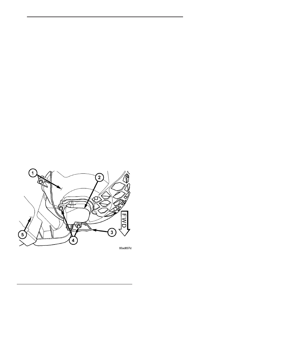
Fig. 29 Recirculation Door Actuator

1 - AIR INLET HOUSING
2 - RECIRCULATION DOOR ACTUATOR
3 - HVAC WIRE HARNESS
4 - SCREW (2)
5 - LOWER HVAC HOUSING

RS

CONTROLS - FRONT

24 - 33

RECIRCULATION DOOR ACTUATOR (Continued)

CONTROLS - REAR

TABLE OF CONTENTS

page

page

A/C-HEATER CONTROL

DESCRIPTION

. . . . . . . . . . . . . . . . . . . . . . . . . 34

OPERATION

. . . . . . . . . . . . . . . . . . . . . . . . . . . 34

REMOVAL

. . . . . . . . . . . . . . . . . . . . . . . . . . . . . 34

INSTALLATION

. . . . . . . . . . . . . . . . . . . . . . . . . 35

BLEND DOOR ACTUATOR

DESCRIPTION

. . . . . . . . . . . . . . . . . . . . . . . . . 36

OPERATION

. . . . . . . . . . . . . . . . . . . . . . . . . . . 36

REMOVAL

. . . . . . . . . . . . . . . . . . . . . . . . . . . . . 36

INSTALLATION

. . . . . . . . . . . . . . . . . . . . . . . . . 37

BLOWER MOTOR RELAY

DESCRIPTION

. . . . . . . . . . . . . . . . . . . . . . . . . 37

OPERATION

. . . . . . . . . . . . . . . . . . . . . . . . . . . 37

REMOVAL

. . . . . . . . . . . . . . . . . . . . . . . . . . . . . 38

INSTALLATION

. . . . . . . . . . . . . . . . . . . . . . . . . 38

BLOWER MOTOR RESISTOR

DESCRIPTION

. . . . . . . . . . . . . . . . . . . . . . . . . 39

OPERATION

. . . . . . . . . . . . . . . . . . . . . . . . . . . 39

DIAGNOSIS AND TESTING

REAR BLOWER MOTOR RESISTOR

. . . . . . . 39

REMOVAL

. . . . . . . . . . . . . . . . . . . . . . . . . . . . . 40

INSTALLATION

. . . . . . . . . . . . . . . . . . . . . . . . . 40

MODE DOOR ACTUATOR

DESCRIPTION

. . . . . . . . . . . . . . . . . . . . . . . . . 40

OPERATION

. . . . . . . . . . . . . . . . . . . . . . . . . . . 40

REMOVAL

. . . . . . . . . . . . . . . . . . . . . . . . . . . . . 41

INSTALLATION

. . . . . . . . . . . . . . . . . . . . . . . . . 41

BLOWER MOTOR POWER MODULE

DESCRIPTION

. . . . . . . . . . . . . . . . . . . . . . . . . 42

OPERATION

. . . . . . . . . . . . . . . . . . . . . . . . . . . 42

REMOVAL

. . . . . . . . . . . . . . . . . . . . . . . . . . . . . 43

INSTALLATION

. . . . . . . . . . . . . . . . . . . . . . . . . 43

A/C-HEATER CONTROL

DESCRIPTION

The rear heating-A/C system is controlled by tem-

perature controls that are centrally mounted directly
into the headliner, or if equipped with the available
DVD player, located in a housing mounted to the
overhead rails. The rear A/C-heater control allows
selection of three blower motor speeds and an Off
position when the center knob on the front A/C-
heater control is set to the Rear position, otherwise
the front A/C-heater control operates both front and
rear heater-A/C operation.

OPERATION

With the rear A/C-heater control active, tempera-

ture selection dictates the air distribution mode (floor
or overhead air) of the rear heater-A/C unit. A cool
temperature setting directs flow to the overhead out-
lets and a warm temperature setting to the floor.
Refer to Body Diagnostic Procedures for further diag-
nostic information.

REMOVAL

OVERHEAD RAIL MOUNTED

(1) Disconnect and isolate the negative battery

cable.

(2) Using a trim stick C-4755 or equivalent, gently

pry the rear A/C-heater control housing off of the
overhead rails. (Fig. 1).

(3) Remove the rear A/C-heater control and hous-

ing assembly from the overhead rails and disconnect

Fig. 1 Rear A/C-Heater Control - MTC System

Shown

1 - REAR A/C-HEATER CONTROL HOUSING
2 - OVERHEAD RAILS
3 - REAR A/C-HEATER CONTROL

24 - 34

CONTROLS - REAR

RS

the wire harness connector(s) from the back of the
control.

(4) If required, remove the three screws that

secure the rear A/C-heater control to the housing and
remove the control from the housing (Fig. 2).

HEADLINER MOUNTED

(1) Disconnect and isolate the negative battery

cable.

(2) Using a trim stick C-4755 or equivalent, gently

pry the top edge of the control bezel away from the
headliner to release the two retaining clips (Fig. 3).

(3) Remove the rear A/C-heater control and bezel

assembly from the headliner and disconnect the wire
harness connector(s) from the back of the control.

(4) If required, remove the three screws that

secure the rear A/C-heater control to the bezel and
remove the control from the bezel (Fig. 4).

INSTALLATION

(1) If required, position the rear A/C-heater control

onto the rear A/C- heater control housing or bezel
(depending on application).

(2) Install the three screws that secure the rear

A/C-heater control to the housing or bezel. Tighten
the screws to 2 N·m (17 in. lbs.).

(3) Position the rear A/C-heater control to the

headliner or overhead rail (depending on application)
and connect the wire harness connector(s) to the rear
of the control.

(4) If headliner mounted, insert the locator tabs on

the back of the rear A/C-heater control bezel over the
forward edge of the opening in the headliner and
using hand pressure, push the rear A/C-heater con-
trol bezel into the headliner until the two retaining
clips fully seat.

(5) If overhead rail mounted, position the top of

the rear A/C-heater control housing over the over-
head rails and using hand pressure, push the rear

Fig. 2 Rear A/C-Heater Control Housing - MTC

System Shown

1 - REAR A/C-HEATER CONTROL HOUSING
2 - WIRE HARNESS CONNECTORS
3 - REAR A/C-HEATER CONTROL
4 - SCREW (3)

Fig. 3 Rear A/C-Heater Control - ATC System Shown

1 - TRIM STICK
2 - BEZEL
3 - REAR A/C-HEATER CONTROL
4 - HEADLINER

Fig. 4 Rear A/C-Heater Control Bezel - ATC System

Shown

1 - BEZEL/VIDEO SCREEN HOUSING (AS EQUIPPED)
2 - SNAP CLIP (2)
3 - REAR A/C-HEATER CONTROL
4 - SCREW (3)
5 - BEZEL LOCATOR TAB (2)

RS

CONTROLS - REAR

24 - 35

A/C-HEATER CONTROL (Continued)

A/C-heater control housing onto the overhead rails
until the retaining clips fully seat.

(6) Reconnect the negative battery cable.
(7) Using the DRB-III

t scan tool, reset the Rear

Temperature Selector calibration values.

(8) Verify that the Actuator Calibration of the

Front Control has passed. If an Actuator Calibration
has not passed correct any errors before proceeding
further.

(9) Rotate the Rear Temperature Selector counter

clockwise to the Cold Position, allow the Selector to
remain in the Cold Position for 5 seconds.

(10) Rotate the Rear Temperature Selector Clock-

wise to the Hot Position, allow the Selector to remain
in the Cold Position for 5 seconds.

(11) Calibration is now complete.

BLEND DOOR ACTUATOR

DESCRIPTION

The rear blend door actuator is a reversible,

12-volt Direct Current (DC), servo motor (Fig. 5). The
single blend door actuator for the rear heating-A/C
system is located on the outboard side of the rear
HVAC housing and is mechanically connected to the
blend-air door.

The rear blend door actuator is interchangeable

with the actuator for the rear mode-air door. Each
actuator is contained within an identical black
molded plastic housing with an integral wire connec-
tor receptacle. Each actuator also has an identical
output shaft with splines that connects it to its
respective door linkage and two integral mounting
tabs that allow the actuator to be secured to the rear
HVAC housing. The blend door actuator does not
require mechanical indexing to the blend-air door, as
it is electronically calibrated by the A/C-heater con-
trol.

The A/C-heater control must be recalibrated each

time an actuator motor is replaced (Refer to 24 -
HEATING & AIR CONDITIONING/CONTROLS -
FRONT/A/C

HEATER

CONTROL

-

STANDARD

PROCEDURE -A/C-HEATER CONTROL CALIBRA-
TION).

OPERATION

The rear blend door actuator is connected to the

front A/C-heater control through the vehicle electrical
system by a dedicated two-wire lead and connector of
the rear HVAC wire harness. The rear blend door
actuator can move the rear blend-air door in two
directions. When the front A/C-heater control pulls
the voltage on one side of the motor connection high
and the other connection low, the rear blend-air door
will move in one direction. When the front A/C-heater

control reverses the polarity of the voltage to the
motor, the rear blend-air door moves in the opposite
direction.

When the front A/C-heater control makes the volt-

age to both connections high or both connections low,
the rear blend-air door stops and will not move.

The front A/C-heater control uses a feedback signal

positioning system to monitor the operation and rel-
ative position of the rear blend door actuator and the
blend-air door. The front A/C-heater control learns
the rear blend-air door stop positions during the cal-
ibration procedure and will store a diagnostic trouble
code (DTC) for any problems it detects in the rear
blend door actuator circuits.

The rear blend door actuator is diagnosed using a

DRBIII

t scan tool. Refer to 9 - Engine Electrical

Diagnostics for more information.

The rear blend door actuator cannot be adjusted or

repaired and, if faulty or damaged, it must be
replaced.

REMOVAL

(1) Disconnect and isolate the negative battery

cable.

(2) Remove the right quarter trim panel and right

D-pillar trim panel from the quarter inner panel
(Refer to 23 - BODY/INTERIOR/QUARTER TRIM
PANEL - REMOVAL).

(3) Remove the two screws that secure the top of

the quarter trim panel attaching bracket to the quar-
ter inner panel.

Fig. 5 Blend Door Actuator

1 - ACTUATOR MOTOR
2 - WIRE CONNECTOR RECEPTACLE
3 - OUTPUT SHAFT
4 - MOUNTING TAB (2)

24 - 36

CONTROLS - REAR

RS

A/C-HEATER CONTROL (Continued)


Content   ..  1215  1216  1217  1218   ..