Content .. 1211 1212 1213 1214 ..
Chrysler RG Voyager. Manual - part 1213
between the compressor front cover and the clutch
coil.
NOTE: A new snap ring must be used to secure the
clutch coil to the A/C compressor. The bevel side of
the snap ring must face outward.
(2) Using snap ring pliers (Special Tool C-4574 or
equivalent), install the external snap ring that
secures the clutch coil to the front cover of the A/C
compressor. The bevel side of the snap ring must face
outward and both snap ring eyelets must be oriented
to the right or the left of the clutch coil dowel pin
location on the A/C compressor. Be certain that the
snap ring is fully and properly seated in the groove.
CAUTION: If the snap ring is not fully seated in the
groove it will vibrate out, resulting in a clutch fail-
ure and severe damage to the compressor front
cover.
(3) Install and securely tighten the screw that
secures the clutch coil pigtail wire connector bracket
and ground clip to the top of the compressor housing.
(4) Install the pulley onto the front cover of the
A/C compressor. If necessary, tap the pulley gently
with a block of wood placed on the pulley friction sur-
face (Fig. 7).
CAUTION: Do not mar the friction surfaces of the
pulley.
NOTE: A new snap ring must be used to secure the
clutch pulley to the A/C compressor. The bevel side
of the snap ring must face outward.
(5) Using snap ring pliers (Special Tool C-4574 or
equivalent), install the external snap ring (bevel side
facing outward) that secures the clutch pulley to the
front cover of the A/C compressor. Be certain that the
snap ring is fully and properly seated in the groove.
(6) If the original clutch plate and clutch pulley
are to be reused, reinstall the original shim(s) on the
compressor shaft against the shoulder. If a new
clutch plate and/or clutch pulley are being used,
install a trial stack of shims 2.54 mm (0.010 in.)
thick on the compressor shaft against the shoulder.
(7) Install the clutch plate onto the compressor
shaft.
NOTE: The shims may compress after tightening
the shaft bolt. Check the air gap in four or more
places to verify the air gap is still correct. Spin the
pulley before performing a final check of the air
gap.
(8) With the clutch plate assembly tight against
the shim(s), measure the air gap between the clutch
plate and the pulley face with feeler gauges. The air
gap should be between 0.35 - 0.60 mm (0.014 - 0.024
in.). If the proper air gap is not obtained, add or sub-
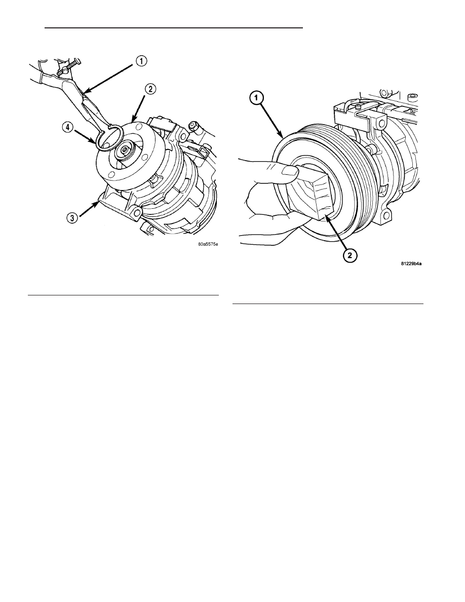
Fig. 6 Remove Clutch Coil Snap Ring
1 - SNAP RING PLIERS
2 - CLUTCH COIL
3 - COMPRESSOR
4 - SNAP RING
Fig. 7 Clutch Pulley - Installation
1 - PULLEY AND BEARING
2 - WOOD BLOCK
RS
CONTROLS - FRONT
24 - 17
A/C COMPRESSOR CLUTCH/COIL (Continued)