Chrysler RG Voyager. Manual - part 1090


  Index      Chrysler     Chrysler RG Voyager - service repair manual 2005 year


Search            


Content   ..  1088  1089  1090  1091   ..


Chrysler RG Voyager. Manual - part 1090


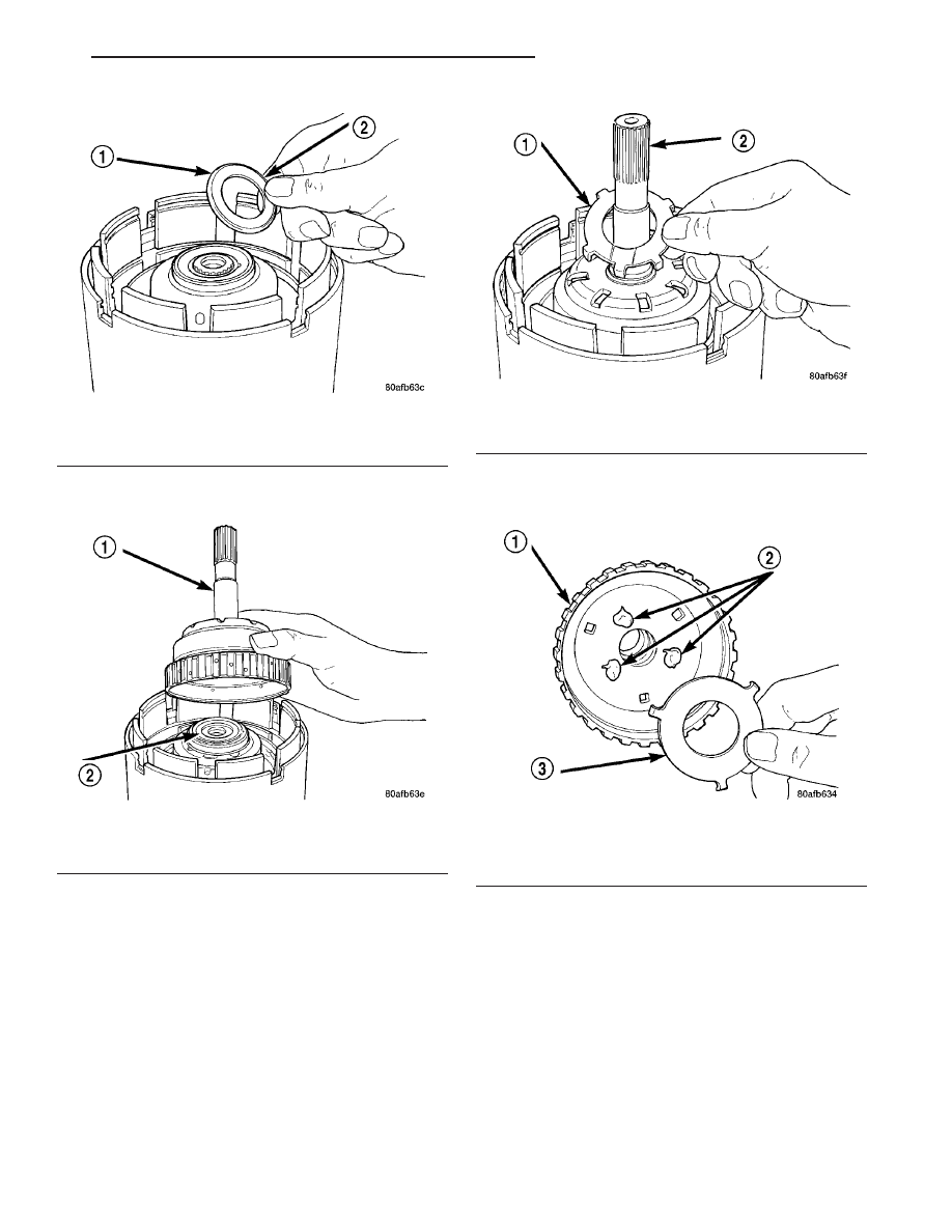
(38) Install the underdrive shaft assembly (Fig.

274).

(39) Install the #3 thrust washer to the underdrive

shaft assembly. Be sure five tabs are seated properly
(Fig. 275).

(40) Install the #3 thrust plate to the bottom of the

overdrive shaft assembly. Retain with petrolatum or
transmission assembly gel (Fig. 276).

(41) Install the overdrive shaft assembly (Fig. 277)

(Fig. 278).

(42) Reinstall overdrive and reverse clutch as

shown. Rechecking these clutch clearances is
not necessary.

Fig. 273 Install No. 2 Needle Bearing

1 - #2 NEEDLE BEARING (NOTE 3 SMALL TABS)
2 - TABS UP

Fig. 274 Install Underdrive Shaft Assembly

1 - UNDERDRIVE SHAFT ASSEMBLY
2 - #2 NEEDLE BEARING

Fig. 275 Install No. 3 Thrust Washer

1 - #3 THRUST WASHER (NOTE 5 TABS)
2 - UNDERDRIVE SHAFT ASSEMBLY

Fig. 276 Install No. 3 Thrust Plate

1 - OVERDRIVE SHAFT ASSEMBLY
2 - DABS OF PETROLATUM (FOR RETENTION)
3 - #3 THRUST PLATE (NOTE 3 TABS)

RS

41TE AUTOMATIC TRANSAXLE

21 - 381

INPUT CLUTCH ASSEMBLY (Continued)

OIL PUMP

DESCRIPTION

The oil pump is located in the pump housing inside

the bell housing of the transaxle case (Fig. 279). The
oil pump consists of an inner and outer gear, a hous-
ing, and a cover that also serves as the reaction shaft
support.

OPERATION

As the torque converter rotates, the converter hub

rotates the inner and outer gears. As the gears
rotate,

the

clearance

between

the

gear

teeth

increases in the crescent area, and creates a suction
at the inlet side of the pump. This suction draws
fluid through the pump inlet from the oil pan. As the
clearance between the gear teeth in the crescent area

Fig. 277 Install Overdrive Shaft Assembly

1 - OVERDRIVE SHAFT ASSEMBLY
2 - #3 THRUST PLATE
3 - #3 THRUST WASHER

Fig. 278 Overdrive/Underdrive Shafts

1 - OVERDRIVE SHAFT
2 - #3 THRUST PLATE (3 TABS)
3 - #3 THRUST WASHER (5 TABS)

4 - UNDERDRIVE SHAFT
5 - #2 NEEDLE BEARING (3 TABS)
6 - INPUT CLUTCH ASSEMBLY

21 - 382

41TE AUTOMATIC TRANSAXLE

RS

INPUT CLUTCH ASSEMBLY (Continued)

decreases, it forces pressurized fluid into the pump
outlet and to the valve body.

DISASSEMBLY

When disassembling the transaxle it is necessary

to inspect the oil pump for wear and damage.

(1) Remove the reaction shaft support-to-pump

body bolts (Fig. 280).

(2) Remove reaction shaft support from pump

housing (Fig. 281).

(3) Remove the pump gears (Fig. 282) and check

for wear and damage on pump housing and gears.

(4) Re-install the gears and check clearances.

Fig. 279 Oil Pump Assembly

1 - PUMP BODY
2 - OUTER GEAR
3 - INNER GEAR
4 - REACTION SHAFT SUPPORT
5 - SEAL RINGS (4)
6 - REACTION SHAFT
7 - CRESCENT

Fig. 280 Reaction Support-to-Pump Body Bolts

1 - BOLT (6)
2 - PUMP BODY
3 - REACTION SHAFT SUPPORT

Fig. 281 Reaction Shaft Support

1 - PUMP BODY
2 - PUMP GEARS
3 - REACTION SHAFT SUPPORT

Fig. 282 Oil Pump Assembly

1 - PUMP BODY
2 - OUTER GEAR
3 - INNER GEAR
4 - REACTION SHAFT SUPPORT
5 - SEAL RINGS (4)
6 - REACTION SHAFT
7 - CRESCENT

RS

41TE AUTOMATIC TRANSAXLE

21 - 383

OIL PUMP (Continued)

(5) Measure the clearance between the outer gear

and the pump pocket (Fig. 283). Clearance should be
0.089–0.202 mm (0.0035-0.0079 in.).

(6) Measure clearance between outer gear and

crescent (Fig. 284). Clearance should be 0.060-0.298
mm (0.0023-0.0117 in.).

(7) Measure clearance between inner gear and

crescent (Fig. 285). Clearance should be 0.093-0.385
mm (0.0036-0.0151 in.).

(8) Position an appropriate piece of Plastigage

across both pump gears.

(9) Align the Plastigage to a flat area on the reac-

tion shaft support housing.

(10) Install the reaction shaft to the pump housing

(Fig. 280). Tighten the bolts to 27 N·m (20 ft. lbs.).

(11) Remove bolts and carefully separate the hous-

ings. Measure the Plastigage following the instruc-
tions supplied.

(12) Clearance between both gear end faces and

the reaction shaft support should be 0.020-0.046 mm
(0.0008-0.0018 in.).

Fig. 283 Measuring Outer Gear-to-Pocket

1 - FEELER GAUGE
2 - OUTER GEAR
3 - PUMP BODY

Fig. 284 Measuring Outer Gear-to-Crescent

1 - FEELER GAUGE
2 - OUTER GEAR
3 - CRESCENT
4 - INNER GEAR

Fig. 285 Measuring Inner Gear-to-Crescent

1 - FEELER GAUGE
2 - OUTER GEAR
3 - CRESCENT
4 - INNER GEAR

21 - 384

41TE AUTOMATIC TRANSAXLE

RS

OIL PUMP (Continued)


Content   ..  1088  1089  1090  1091   ..