Chrysler RG Voyager. Manual - part 1080


  Index      Chrysler     Chrysler RG Voyager - service repair manual 2005 year


Search            


Content   ..  1078  1079  1080  1081   ..


Chrysler RG Voyager. Manual - part 1080


OPERATION

The function of an accumulator is to cushion the

application of a frictional clutch element. When pres-
surized fluid is applied to a clutch circuit, the appli-
cation force is dampened by fluid collecting in the
respective accumulator chamber against the piston
and spring(s). The intended result is a smooth, firm
clutch application.

DRIVING CLUTCHES

DESCRIPTION

Three hydraulically applied input clutches are used

to drive planetary components. The underdrive, over-
drive, and reverse clutches are considered input
clutches and are contained within the input clutch
assembly (Fig. 167). The input clutch assembly also
contains:

• Input shaft

• Input hub

• Clutch retainer

• Underdrive piston

• Overdrive/reverse piston

• Overdrive hub

• Underdrive hub

OPERATION

The three input clutches are responsible for driving

different components of the planetary geartrain.

NOTE: Refer to the “Elements In Use” chart in Diag-
nosis and Testing for a collective view of which
clutch elements are applied at each position of the
selector lever.

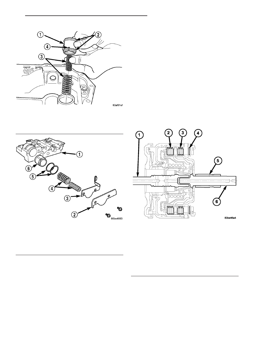
Fig. 165 Low/Reverse Accumulator Assembly

1 - ACCUMULATOR PISTON
2 - SEAL RINGS
3 - RETURN SPRINGS
4 - (NOTE NOTCH)

Fig. 166 2/4 Accumulator Assembly

1 - VALVE BODY
2 - RETAINER PLATE
3 - DETENT SPRING
4 - SPRINGS
5 - SEALS
6 - PISTON

Fig. 167 Input Clutch Assembly

1 - INPUT SHAFT
2 - UNDERDRIVE CLUTCH
3 - OVERDRIVE CLUTCH
4 - REVERSE CLUTCH
5 - OVERDRIVE SHAFT
6 - UNDERDRIVE SHAFT

RS

41TE AUTOMATIC TRANSAXLE

21 - 341

ACCUMULATOR (Continued)

UNDERDRIVE CLUTCH

The underdrive clutch is hydraulically applied in

first, second, and third (direct) gears by pressurized
fluid against the underdrive piston. When the under-
drive clutch is applied, the underdrive hub drives the
rear sun gear.

OVERDRIVE CLUTCH

The overdrive clutch is hydraulically applied in

third (direct) and overdrive gears by pressurized fluid
against the overdrive/reverse piston. When the over-
drive clutch is applied, the overdrive hub drives the
front planet carrier.

REVERSE CLUTCH

The reverse clutch is hydraulically applied in

reverse gear only by pressurized fluid against the
overdrive/reverse piston. When the reverse clutch is
applied, the front sun gear assembly is driven.

FINAL DRIVE

DESCRIPTION

The 41TE differential is a conventional open

design. It consists of a ring gear and a differential
case. The differential case consists of pinion and side
gears, and a pinion shaft. The differential case is
supported in the transaxle by tapered roller bearings
(Fig. 168).

OPERATION

The differential assembly is driven by the transfer

shaft by way of the differential ring gear. The ring
gear drives the differential case, and the case drives
the driveshafts through the differential gears. The
differential pinion and side gears are supported in
the case by thrust washers and a pinion shaft. Dif-
ferential pinion and side gears make it possible for
front tires to rotate at different speeds while corner-
ing.

DISASSEMBLY

The transfer shaft should be removed for differen-

tial repair and bearing turning torque checking.

(1) Remove the differential cover and bolts (Fig.

169) (Fig. 170).

Fig. 168 Differential Assembly

1 - DIFFERENTIAL CASE
2 - RING GEAR
3 - TRANSFER SHAFT
4 - PINION GEAR
5 - PINION SHAFT
6 - SIDE GEAR

Fig. 169 Differential Cover Bolts

1 - DIFFERENTIAL COVER BOLTS
2 - DIFFERENTIAL COVER

Fig. 170 Remove Differential Cover

1 - DIFFERENTIAL ASSEMBLY
2 - DIFFERENTIAL COVER

21 - 342

41TE AUTOMATIC TRANSAXLE

RS

DRIVING CLUTCHES (Continued)

(2) Remove the differential bearing retainer and

bolts (Fig. 171) (Fig. 172).

(3) Using a plastic hammer, remove extension

housing/adapter plate on the right side of the trans-
axle.

WARNING: HOLD ONTO DIFFERENTIAL ASSEMBLY
TO PREVENT IT FROM ROLLING OUT OF HOUSING.

(4) Use Miller Special Tool 5048, 5048-3 Collets,

and L-4539-2 Button to remove the differential bear-
ing cone on the extension housing side.

(5) Use Miller Special Tool 5048, 5048-4 Collets,

and L-4539-2 Button to remove the differential bear-
ing cone on the bearing retainer side (Fig. 173) (Fig.
174) (Fig. 175).

Fig. 171 Differential Retainer Bolts

1 - DIFFERENTIAL RETAINER BOLTS

Fig. 172 Remove Bearing Retainer

1 - DIFFERENTIAL BEARING RETAINER
2 - TOOL L-4435

Fig. 173 Position Button and Collets Onto

Differential and Bearing (Ring Gear Side)

1 - SPECIAL TOOL L-4539-2
2 - SPECIAL TOOL 5048
3 - SPECIAL TOOL 5048-4

Fig. 174 Position Tool 5048 Over Button and Collets

at Differential Bearing (Ring Gear Side)

1 - SPECIAL TO0L 5048
2 - DIFFERENTIAL
3 - SPECIAL TOOL 5048-4

RS

41TE AUTOMATIC TRANSAXLE

21 - 343

FINAL DRIVE (Continued)

(6) Using Miller Special Tool L-4518, remove the

differential bearing race from the extension housing.

(7) Using Miller Special Tool 6062A, remove the

differential bearing race from the bearing retainer
(Fig. 176) (Fig. 177).

(8) Remove ring gear-to-differential case bolts and

floating pinion shaft retainers (Fig. 178).

(9) Separate ring gear from differential case (Fig.

179).

Fig. 175 Remove Differential Bearing Cone (Ring

Gear Side)

1 - SPECIAL TOOL 5048
2 - RING GEAR

Fig. 176 Position Bearing Cup Remover Tool in

Retainer

1 - SPECIAL TOOL 6062A
2 - DIFFERENTIAL BEARING RETAINER

Fig. 177 Remove Bearing Cup

1 - SPECIAL TOOL 6062A
2 - DIFFERENTIAL BEARING RETAINER

Fig. 178 Ring Gear-to-Case Bolts

1 - DIFFERENTIAL CASE
2 - PINION SHAFT RETAINER
3 - RING GEAR
4 - RING GEAR-TO-CASE BOLT

21 - 344

41TE AUTOMATIC TRANSAXLE

RS

FINAL DRIVE (Continued)


Content   ..  1078  1079  1080  1081   ..