Chrysler Pacifica. Manual - part 896


  Index      Chrysler     Chrysler Pacifica - service repair manual 2005 year


Search            


Content   ..  894  895  896  897   ..


Chrysler Pacifica. Manual - part 896


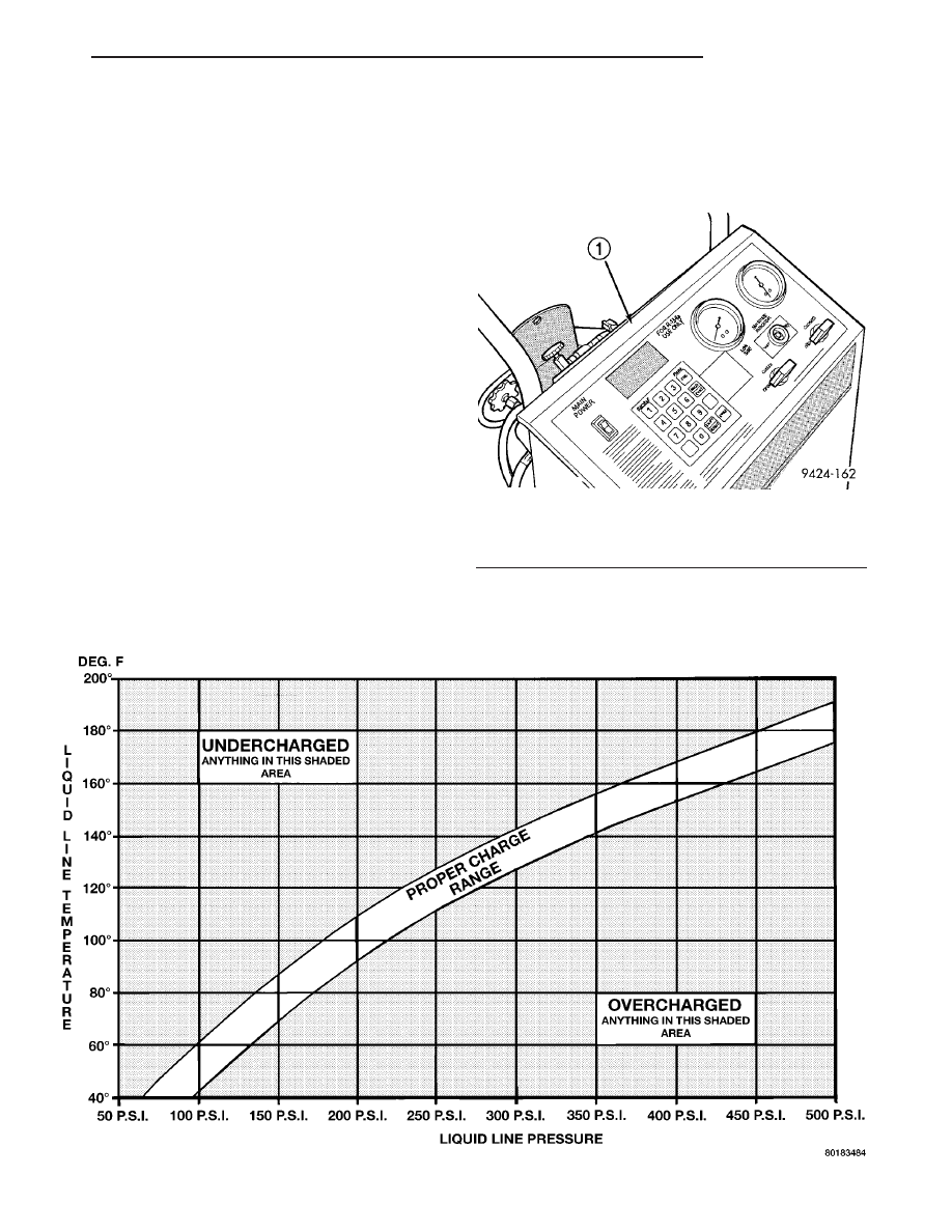
(6) Recheck the refrigerant system charge level fol-

lowing each refrigerant level adjustment. Continue
this process until the refrigerant system readings are
in the proper charge range area on the Charge Deter-
mination Chart.

STANDARD PROCEDURE

REFRIGERANT SYSTEM SERVICE EQUIPMENT

WARNING: Eye protection must be worn when servic-
ing an air conditioning refrigerant system. Turn off
(rotate clockwise) all valves on the equipment being
used before connecting to, or disconnecting from the
refrigerant system. Failure to observe these warnings
may result in personal injury or death.

WARNING: Review the warnings and cautions in the
front of this section before performing the following
operation (Refer to 24 - HEATING & AIR CONDITION-
ING/PLUMBING - WARNINGS) and (Refer to 24 - HEAT-
ING & AIR CONDITIONING/PLUMBING - CAUTIONS).

RECOVERY/RECYCLING STATION

When servicing the A/C system, a R-134a refrigerant

recovery/recycling/charging station that meets SAE

standard J2210 must be used (Fig. 2). Contact an auto-
motive service equipment supplier for refrigerant recov-
ery/recycling/charging equipment. Refer to the operating
instructions supplied by the equipment manufacturer
for proper care and use of this equipment.

Fig. 1 Charge Determination Chart (Ambient Test Condition 85° F)

Fig. 2 Refrigerant Recovery/Recycling Station -

Typical

1 - R-134a REFRIGERANT STATION

CS

PLUMBING

24 - 61

PLUMBING (Continued)

MANIFOLD GAUGE SET

CAUTION: Do not use an R-12 manifold gauge set
on an R-134a system. The refrigerants are not com-
patible and system damage will result.

A manifold gauge set (Fig. 3) may be needed with

some

recovery/recycling/charging

equipment.

The

manifold gauge set should have manual shut-off
valves, or automatic back-flow valves located at the
service port connector end of the manifold gauge set
hoses. This will prevent refrigerant from being
released into the atmosphere.

MANIFOLD GAUGE SET CONNECTIONS

CAUTION: Do not use an R-12 manifold gauge set
on an R-134a system. The refrigerants are not com-
patible and system damage will result.

• LOW PRESSURE GAUGE HOSE - The low

pressure hose (Blue with Black stripe) attaches to
the suction (low side) service port. This port is on the
A/C suction line located near the A/C expansion valve
at the rear of the engine compartment.

• HIGH PRESSURE GAUGE HOSE - The high

pressure hose (Red with Black stripe) attaches to the
discharge (high side) service port. This port is on the

liquid line fitting located at the top of the receiver/
drier near the right strut tower.

• RECOVERY, RECYCLING, EVACUATION

AND CHARGING HOSE - The center manifold
hose (Yellow, or White, with Black stripe) is used to
recover, evacuate, and charge the refrigerant system.
When the low or high pressure valves on the mani-
fold gauge set are opened, the refrigerant in the sys-
tem will escape through this hose.

REFRIGERANT SYSTEM RECOVERY

WARNING: Refer to the applicable warnings and
cautions for this system before performing the fol-
lowing operation (Refer to 24 - HEATING & AIR
CONDITIONING/PLUMBING - WARNINGS) and (Refer
to 24 - HEATING & AIR CONDITIONING/PLUMBING -
CAUTIONS). Failure to follow the warnings and cau-
tions could result in possible personal injury or
death.

A R-134a refrigerant recovery/recycling/charging

station that meets SAE Standard J2210 must be
used to recover the refrigerant from an R-134a refrig-
erant system. Refer to the operating instructions sup-
plied by the equipment manufacturer for the proper
care and use of this equipment.

REFRIGERANT SYSTEM EVACUATE

NOTE: Special effort must be used to prevent mois-
ture from entering the A/C system oil. Moisture in
the oil is very difficult to remove and will cause a
reliability problem with the compressor.

If an A/C compressor designed to use R-134a refrig-

erant is left open to the atmosphere for an extended
period of time, it is recommended that the refrigerant
oil be drained and replaced with new oil or a new
compressor be used. This will eliminate the possibil-
ity of contaminating the A/C refrigerant system.

If the refrigerant system has been open to the

atmosphere, it must be evacuated before the refriger-
ant system can be filled. Moisture and air mixed
with the refrigerant system will raise the compressor
head pressure above acceptable operating levels. This
will reduce the performance of the A/C system and
damage the A/C compressor. Moisture will boil at
near room temperature when exposed to vacuum. A
R-134a refrigerant recovery/recycling/charging sta-
tion that meets SAE Standard J2210 must be used to
evacuate the refrigerant system. See the operating
instructions supplied by the equipment manufacturer
for proper care and use of this equipment. To evacu-
ate the refrigerant system, use the following proce-
dure:

Fig. 3 Manifold Gauge Set - Typical

1 - HIGH PRESSURE GAUGE
2 - VALVE
3 - VACUUM/REFRIGERANT HOSE (YELLOW W/BLACK STRIPE)
4 - HIGH PRESSURE HOSE (RED W/BLACK STRIPE)
5 - LOW PRESSURE HOSE (BLUE W/BLACK STRIPE)
6 - VALVE
7 - LOW PRESSURE GAUGE

24 - 62

PLUMBING

CS

PLUMBING (Continued)

NOTE: When connecting the service equipment
couplings to the refrigerant system service ports,
be certain that the valve of each coupling is fully
closed. This will reduce the amount of effort
required to make the connection.

(1) Recover the refrigerant system (Refer to 24 -

HEATING & AIR CONDITIONING/PLUMBING -
STANDARD PROCEDURE - REFRIGERANT SYS-
TEM RECOVERY).

(2) Connect a suitable charging station, refrigerant

recovery machine or a manifold gauge set with vac-
uum pump and refrigerant recovery equipment.

(3) Open the suction and discharge valves and

start the vacuum pump. The vacuum pump should
run a minimum of 45 minutes prior to charge to
eliminate all moisture within the refrigerant system.
When the suction gauge reads -88 kPa (-26 in. Hg)
vacuum or greater for 30 minutes, close all valves
and turn off vacuum pump. If the refrigerant system
fails to reach the specified vacuum, the refrigerant
system likely has a leak that must be corrected. If
the refrigerant system maintains specified vacuum
for at least 30 minutes, start the vacuum pump, open
the suction and discharge valves. Then allow the sys-
tem to evacuate an additional 10 minutes.

(4) Close all valves. Turn off and disconnect the

vacuum pump.

(5) Charge the refrigerant system (Refer to 24 -

HEATING & AIR CONDITIONING/PLUMBING -
STANDARD PROCEDURE - REFRIGERANT SYS-
TEM CHARGE).

REFRIGERANT SYSTEM CHARGE

WARNING: Refer to the applicable warnings and
cautions for this system before performing the fol-
lowing operation (Refer to 24 - HEATING & AIR
CONDITIONING/PLUMBING - WARNINGS) and (Refer
to 24 - HEATING & AIR CONDITIONING/PLUMBING -
CAUTIONS). Failure to follow the warnings and cau-
tions could result in possible personal injury or
death.

NOTE: Always refer to the A/C Underhood Specifi-
cation Label for the refrigerant fill capacity of the
vehicle being serviced.

After all refrigerant system leaks have been

repaired and the refrigerant system has been evacu-
ated, a refrigerant charge can be injected into the
system. For the proper amount of the refrigerant
charge, always refer to the A/C Underhood Specifica-
tion Label located in the engine compartment. An
R-134a refrigerant recovery/recycling/charging sta-
tion that meets SAE Standard J2210 must be used to

charge the refrigerant system with R-134a refriger-
ant. See the operating instructions supplied by the
equipment manufacturer for proper care and use of
this equipment.

CHARGING PROCEDURE

CAUTION: A small amount of refrigerant oil is
removed from the A/C system each time the refrig-
erant system is recovered and evacuated. Before
charging the A/C system, you MUST replenish any
oil lost during the recovery process. Refer the
equipment manufacturer instructions for more infor-
mation.

(1) Evacuate the refrigerant system (Refer to 24 -

HEATING & AIR CONDITIONING/PLUMBING -
STANDARD PROCEDURE - REFRIGERANT SYS-
TEM EVACUATE).

(2) A manifold gauge set and a R-134a refrigerant

recovery/recycling/charging station that meets SAE
standard J2210 should still be connected to the A/C
refrigerant system.

(3) Measure the proper amount of R-134a refriger-

ant and heat it to 52° C (125° F) with the charging
station. See the operating instructions supplied by
the equipment manufacturer for proper use of this
equipment.

(4) Open both the suction and discharge valves,

then open the charge valve to allow the heated
refrigerant to flow into the system.

(5) When the transfer of refrigerant has stopped,

close both the suction and discharge valves.

(6) If all of the refrigerant charge did not transfer

from the dispensing device, open all of the windows
in the vehicle and set the A/C-heater controls so that
the A/C compressor is engaged and the blower motor
is operating at its lowest speed setting. Run the
engine at a steady high idle (about 1400 rpm). If
theA/C compressor will not engage, test the compres-
sor clutch control circuit and repair as required.

(7) Open the suction valve to allow the remaining

refrigerant to transfer to the refrigerant system.

WARNING: Take care not to open the discharge
(high pressure) valve at this time.

(8) Close the suction valve and test the A/C system

performance (Refer to 24 - HEATING & AIR CONDI-
TIONING - STANDARD PROCEDURE - A/C PER-
FORMANCE TEST).

(9) Disconnect the charging station and manifold

gauge set from the refrigerant system service ports.

(10) Install the caps onto the refrigerant system

service ports.

(11) Run the HVAC Control Cooldown test to ver-

ify proper operation (Refer to 24 - HEATING & AIR

CS

PLUMBING

24 - 63

PLUMBING (Continued)

CONDITIONING - DIAGNOSIS AND TESTING -
A/C COOLDOWN TEST).

A/C COMPRESSOR

DESCRIPTION

DESCRIPTION

Vehicles equipped with the 3.8L gasoline engine

use the Denso 10S17 A/C compressor. Vehicles
equipped with the 3.5L gasoline engine use the
Denso 10S20 A/C compressor. Both A/C compressors
include an integral high pressure relief valve. The
A/C compressor (Fig. 4) is secured to a mounting
bracket.

HIGH PRESSURE RELIEF VALVE

A high pressure relief valve is located on the rear

of the A/C compressor. This mechanical valve is
designed to vent refrigerant from the A/C system to
protect against damage to the compressor and other
system components, caused by condenser air flow
restriction or an overcharge of refrigerant.

OPERATION

A/C COMPRESSOR

The A/C compressor is driven by the engine

through an electric clutch, drive pulley and belt
arrangement. The A/C compressor is lubricated by

refrigerant oil that is circulated throughout the
refrigerant system with the refrigerant.

The A/C compressor draws in low-pressure refrig-

erant vapor from the A/C evaporator through its suc-
tion port. It then compresses the refrigerant into a
high-pressure, high-temperature refrigerant vapor.
The A/C compressor pumps the high-pressure refrig-
erant vapor to the A/C condenser through the com-
pressor discharge port.

The A/C compressor cannot be repaired and, if

faulty or damaged, the entire compressor assembly
must be replaced. The compressor clutch, pulley and
clutch coil are available for service.

HIGH PRESSURE RELIEF VALVE

The high pressure relief valve vents refrigerant

from the A/C system when a discharge pressure of
3445 to 4135 kPa (500 to 600 psi) or above is
reached. The relief valve closes when a minimum dis-
charge pressure of 2756 kPa (400 psi) is reached.

The high pressure relief valve vents only enough

refrigerant to reduce the A/C system pressure, and
then re-seats itself. The majority of the refrigerant is
conserved in the A/C system. If the relief valve vents
refrigerant, it does not necessarily mean that the
valve is faulty.

The high pressure relief valve is a factory-cali-

brated unit. The relief valve cannot be adjusted or
repaired, and must not be removed or otherwise dis-
turbed. The relief valve is only serviced as a part of
the A/C compressor assembly.

DIAGNOSIS AND TESTING

A/C COMPRESSOR NOISE

When investigating an A/C system related noise,

you must first know the conditions under which the
noise occurs. These conditions include: weather, vehi-
cle speed, transmission in gear or neutral, engine
speed, engine temperature, and any other special
conditions. Noises that develop during A/C operation
can often be misleading. For example: What sounds
like a failed front engine bearing or connecting rod,
may be caused by loose bolts, nuts, mounting brack-
ets or a loose compressor clutch assembly.

Drive belts are speed sensitive. At different engine

speeds and depending upon drive belt tension, drive
belts can develop noises that are mistaken for an A/C
compressor noise. Improper drive belt tension can
cause a misleading noise when the compressor clutch
is engaged, which may not occur when the compres-
sor clutch is disengaged. Check the accessory drive
belt condition and tension as described in Cooling
before beginning this procedure.

Fig. 4 Denso Compressor -Typical

1 - A/C COMPRESSOR
2 - REFRIGERANT LINE PORTS
3 - HIGH PRESSURE RELIEF VALVE

24 - 64

PLUMBING

CS

PLUMBING (Continued)


Content   ..  894  895  896  897   ..