Chrysler Pacifica. Manual - part 888


  Index      Chrysler     Chrysler Pacifica - service repair manual 2005 year


Search            


Content   ..  886  887  888  889   ..


Chrysler Pacifica. Manual - part 888


OPERATION

The dual infrared temperature sensors provide

independent measurement inputs to the automatic
temperature control (ATC) A/C-heater control module
that indicates the surface temperature of the driver
seat and front seat passenger seat occupants. By
using a surface temperature measurement, rather
than an air temperature measurement, the ATC sys-
tem is able to adjust itself to the comfort level as per-
ceived by the occupant. This allows the system to
detect and compensate for other ambient conditions
affecting comfort levels, such as solar heat gain or
evaporative heat loss. The ATC system logic responds
to the infrared sensor inputs by calculating and
adjusting the air flow temperature and air flow rate
needed to properly obtain and maintain the individ-
ually selected comfort level temperatures of both the
driver and passenger seat occupants.

The ATC A/C-heater control module continually

monitors the infrared sensor circuits, and will store a
diagnostic trouble code (DTC) for any problem it
detects. The infrared temperature sensor is diag-
nosed using a DRBIII

t scan tool. Refer to Body Diag-

nostic Procedures.

The

infrared

sensors

cannot

be

adjusted

or

repaired and, if faulty or damaged, the A/C-heater
control must be replaced.

MODE DOOR ACTUATOR

DESCRIPTION

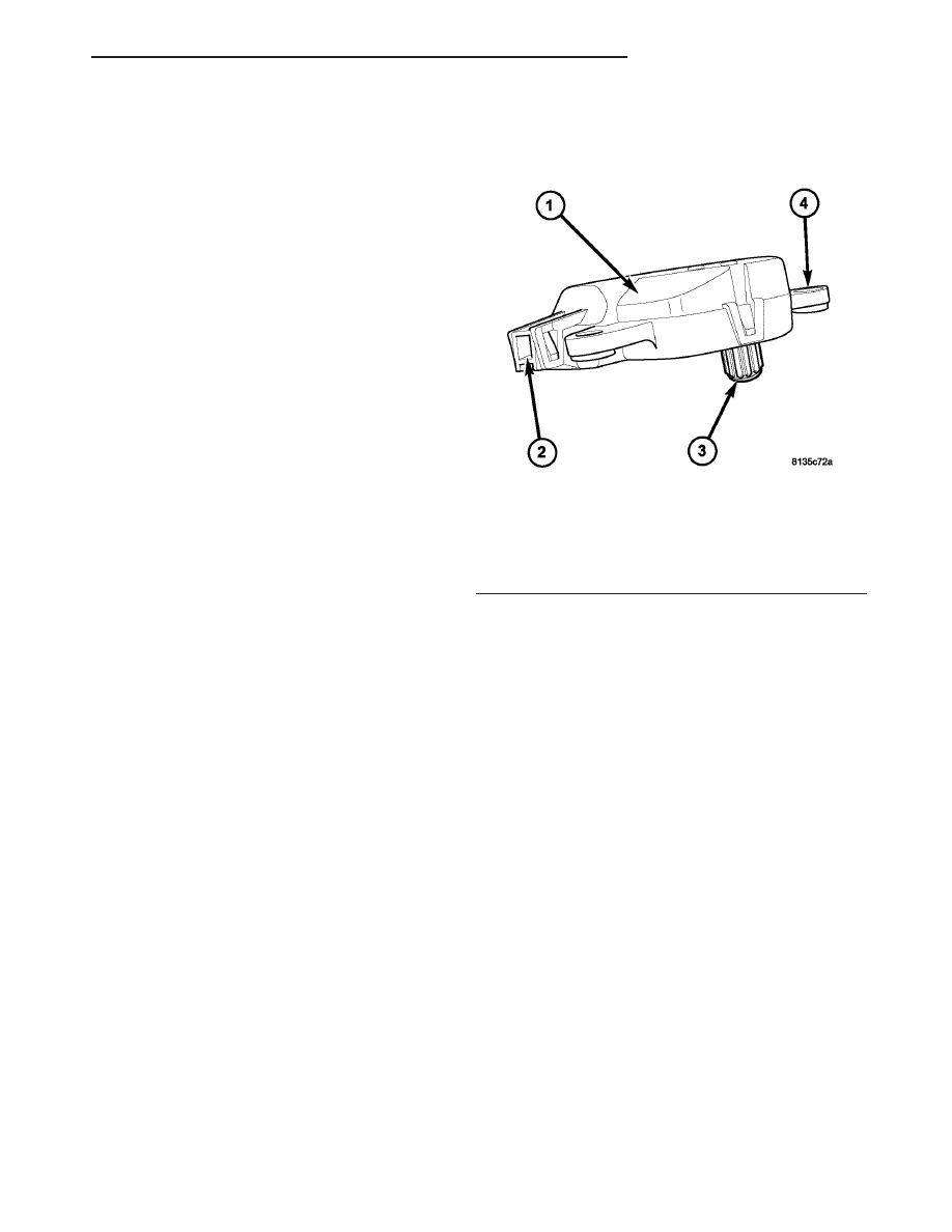
The mode door actuator for the heating-A/C system

is a reversible, 12-volt Direct Current (DC), servo
motor (Fig. 23). The single mode door actuator is
located on the driver side end of the HVAC air dis-
tribution housing, close to the top of the housing. The
mode door actuator is mechanically connected to the
mode-air doors.

The mode door actuator is interchangeable with

the actuators for the blend-air doors and the recircu-
lation-air door. Each actuator is contained within an
identical black molded plastic housing with an inte-
gral wire connector receptacle. Each actuator also
has an identical output shaft with splines that con-
nects it to its respective door linkage and two inte-
gral mounting tabs that allow the actuator to be
secured to the HVAC housing. The mode door actua-
tor does not require mechanical indexing to the
mode-air doors, as it is electronically calibrated by
the A/C-heater control.

The A/C-heater control must be recalibrated each

time an actuator motor is replaced (Refer to 24 -
HEATING & AIR CONDITIONING/CONTROLS -
FRONT/A/C

HEATER

CONTROL

-

STANDARD

PROCEDURE -A/C-HEATER CONTROL CALIBRA-
TION).

OPERATION

The mode door actuator is connected to the A/C-

heater control through the vehicle electrical system
by a dedicated two-wire lead and connector of the
HVAC wire harness. The mode door actuator can
move the mode-air doors in two directions. When the
A/C-heater control pulls the voltage on one side of
the motor connection high and the other connection
low, the mode-air doors will move in one direction.
When the A/C-heater control reverses the polarity of
the voltage to the motor, the mode-air doors move in
the opposite direction.

When the A/C-heater control makes the voltage to

both connections high or both connections low, the
mode-air doors stop and will not move.

The A/C-heater control uses a feedback signal posi-

tioning system to monitor the operation and relative
position of the mode door actuator and the mode-air
doors. The A/C-heater control learns the mode-air
doors stop positions during the calibration procedure
and will store a diagnostic trouble code (DTC) for any
problems it detects in the mode door actuator cir-
cuits.

The mode door actuator is diagnosed using a

DRBIII

t scan tool. Refer to 9 - Engine Electrical

Diagnostics for more information.

The mode door actuator cannot be adjusted or

repaired and, if faulty or damaged, it must be
replaced.

Fig. 23 Mode Door Actuator

1 - ACTUATOR MOTOR
2 - WIRE CONNECTOR RECEPTACLE
3 - OUTPUT SHAFT
4 - MOUNTING TAB (2)

CS

CONTROLS - FRONT

24 - 29

INFRARED TEMPERATURE SENSOR (Continued)

REMOVAL

WARNING: On vehicles equipped with airbags, dis-
able the airbag system before attempting any steer-
ing wheel, steering column, or instrument panel
component diagnosis or service. Disconnect and
isolate the negative battery (ground) cable, then
wait two minutes for the airbag system capacitor to
discharge before performing further diagnosis or
service. This is the only sure way to disable the air-
bag system. Failure to take the proper precautions
could result in accidental airbag deployment and
possible personal injury or death.

(1) Disconnect and isolate the negative battery

cable.

(2) Remove the silencer from beneath the driver

side end of the instrument panel. (Refer to 23 -
BODY/INSTRUMENT

PANEL/INSTRUMENT

PANEL SILENCER - REMOVAL).

(3) Disconnect the wire harness connector from the

mode door actuator (Fig. 24).

(4) Remove the two screws that secure the mode

door actuator to the HVAC air distribution housing
and remove the actuator.

INSTALLATION

(1) Position the mode door actuator onto the HVAC

air distribution housing. If necessary, rotate the
actuator slightly to align the splines on the actuator
output shaft with those in the mode door linkage.

(2) Install the two screws that secure the mode

door actuator to the air distribution housing. Tighten
the screws to 2 N·m (17 in. lbs.).

(3) Connect the wire harness connector to the

mode door actuator.

(4) Install the silencer under the driver side end of

the instrument panel (Refer to 23 - BODY/INSTRU-
MENT PANEL/INSTRUMENT PANEL SILENCER -
INSTALLATION).

(5) Reconnect the negative battery cable and cali-

brate the A/C-heater control (Refer to 24 - HEATING
& AIR CONDITIONING/CONTROLS - FRONT/A/C
HEATER CONTROL - STANDARD PROCEDURE
-A/C-HEATER CONTROL CALIBRATION).

RECIRCULATION DOOR
ACTUATOR

DESCRIPTION

The recirculation door actuator is a reversible, 12

volt direct current (DC), servo motor (Fig. 25). The
recirculation door actuator is located on the bottom of
the HVAC air inlet housing and is directly connected
to the pivot shaft of the recirculation-air door.

The recirculation door actuator is interchangeable

with the actuators for the blend-air door(s) and the
mode-air doors. Each actuator is contained within an
identical black molded plastic housing with an inte-
gral wire connector receptacle. Each actuator also
has an identical output shaft with splines that con-
nects it to its door linkage and two integral mounting
tabs that allow the actuator to be secured to the air
inlet housing. The recirculation door actuator does
not require mechanical indexing to the recirculation-
air door, as it is electronically calibrated by the A/C-
heater control.

The A/C-heater control must be recalibrated each

time an actuator motor is replaced (Refer to 24 -
HEATING & AIR CONDITIONING/CONTROLS -
FRONT/A/C

HEATER

CONTROL

-

STANDARD

PROCEDURE -A/C-HEATER CONTROL CALIBRA-
TION).

OPERATION

The recirculation door actuator is connected to the

A/C-heater control through the vehicle electrical sys-
tem by a dedicated two-wire lead and connector of
the HVAC wire harness. The recirculation door
actuator can move the recirculation-air door in two
directions. When the A/C-heater control pulls the
voltage on one side of the motor connection high and
the other connection low, the recirculation-air door
will move in one direction. When the A/C-heater con-
trol reverses the polarity of the voltage to the motor,
the recirculation-air door moves in the opposite direc-
tion.

Fig. 24 Mode Door Actuator

1 - WIRE HARNESS CONNECTOR
2 - MODE DOOR ACTUATOR
3 - SCREW (2)
4 - DRIVER BLEND DOOR ACTUATOR (DUAL-ZONE)
5 - HEATER CORE
6 - BLEND DOOR ACTUATOR

24 - 30

CONTROLS - FRONT

CS

MODE DOOR ACTUATOR (Continued)

When the A/C-heater control makes the voltage to

both connections high or both connections low, the
recirculation-air door stops and will not move.

The A/C-heater control uses a feedback signal posi-

tioning system to monitor the operation and relative
position of the recirculation door actuator and the
recirculation-air door. The A/C-heater control learns
the recirculation-air door stop positions during the
calibration procedure and will store a diagnostic
trouble code (DTC) for any problems it detects in the
recirculation door actuator circuits.

The recirculation door actuator is diagnosed using

a DRBIII

t scan tool. Refer to 9 - Engine Electrical

Diagnostics for more information.

The recirculation door actuator cannot be adjusted

or repaired and, if faulty or damaged, it must be
replaced.

REMOVAL

WARNING: On vehicles equipped with airbags, dis-
able the airbag system before attempting any steer-
ing wheel, steering column, or instrument panel
component diagnosis or service. Disconnect and
isolate the negative battery (ground) cable, then
wait two minutes for the airbag system capacitor to
discharge before performing further diagnosis or
service. This is the only sure way to disable the air-
bag system. Failure to take the proper precautions
could result in accidental airbag deployment and
possible personal injury or death.

(1) Disconnect and isolate the negative battery

cable.

(2) Pull the carpet on the passenger side front

floor away from the dash panel far enough to access
the recirculation door actuator.

(3) Disconnect the HVAC wire harness connector

from the recirculation door actuator (Fig. 26).

(4) Remove the two screws that secure the recircu-

lation door actuator to the air inlet housing and
remove the actuator.

INSTALLATION

(1) Position the recirculation door actuator onto

the air inlet housing. If necessary, rotate the actuator
slightly to align the splines on the actuator output
shaft with those in the recirculation-air door pivot
shaft.

(2) Install the two screws that secure the recircu-

lation door actuator to the air inlet housing. Tighten
the screws to 2 N·m (17 in. lbs.).

(3) Connect the HVAC wire harness connector to

the recirculation door actuator.

(4) Reposition the carpet on the passenger side

front floor back up to the dash panel.

(5) Reconnect the negative battery cable and cali-

brate the A/C-heater control (Refer to 24 - HEATING
& AIR CONDITIONING/CONTROLS - FRONT/A/C
HEATER CONTROL - STANDARD PROCEDURE
-A/C-HEATER CONTROL CALIBRATION).

Fig. 25 Recirculation Door Actuator

1 - ACTUATOR MOTOR
2 - WIRE CONNECTOR RECEPTACLE
3 - OUTPUT SHAFT
4 - MOUNTING TAB (2)

Fig. 26 Recirculation Door Actuator

1 - AIR INLET HOUSING
2 - RECIRCULATION DOOR ACTUATOR
3 - HVAC WIRE HARNESS
4 - SCREW (2)
5 - LOWER HVAC HOUSING

CS

CONTROLS - FRONT

24 - 31

RECIRCULATION DOOR ACTUATOR (Continued)

CONTROLS - REAR

TABLE OF CONTENTS

page

page

BLOWER MOTOR RELAY

DESCRIPTION

. . . . . . . . . . . . . . . . . . . . . . . . . 32

OPERATION

. . . . . . . . . . . . . . . . . . . . . . . . . . . 32

REMOVAL

. . . . . . . . . . . . . . . . . . . . . . . . . . . . . 33

INSTALLATION

. . . . . . . . . . . . . . . . . . . . . . . . . 33

BLOWER MOTOR SWITCH

DESCRIPTION

. . . . . . . . . . . . . . . . . . . . . . . . . 33

OPERATION

. . . . . . . . . . . . . . . . . . . . . . . . . . . 33

REMOVAL

. . . . . . . . . . . . . . . . . . . . . . . . . . . . . 33

INSTALLATION

. . . . . . . . . . . . . . . . . . . . . . . . . 34

MODE DOOR ACTUATOR

DESCRIPTION

. . . . . . . . . . . . . . . . . . . . . . . . . 34

OPERATION

. . . . . . . . . . . . . . . . . . . . . . . . . . . 34

REMOVAL

. . . . . . . . . . . . . . . . . . . . . . . . . . . . . 35

INSTALLATION

. . . . . . . . . . . . . . . . . . . . . . . . . 35

BLOWER MOTOR POWER MODULE

DESCRIPTION

. . . . . . . . . . . . . . . . . . . . . . . . . 35

OPERATION

. . . . . . . . . . . . . . . . . . . . . . . . . . . 36

REMOVAL

. . . . . . . . . . . . . . . . . . . . . . . . . . . . . 36

INSTALLATION

. . . . . . . . . . . . . . . . . . . . . . . . . 36

BLOWER MOTOR RELAY

DESCRIPTION

The rear blower motor relay used in the rear cen-

ter floor console when equipped with the automatic
temperature control (ATC) heating-A/C system is a
International

Standards

Organization

(ISO)-type

relay (Fig. 1). Relays conforming to the ISO specifi-
cations have common physical dimensions, current
capacities, terminal functions and patterns.

The rear blower motor relay is located in the inte-

grated power module (IPM) in the engine compart-
ment.

OPERATION

The rear blower motor relay is an electromechani-

cal switch that uses a low current input from the
front control module (FCM) to control the high cur-
rent output to the rear blower motor power module.
The movable, common feed relay contact is held
against the fixed, normally closed relay contact by

spring pressure. When the electromagnetic relay coil
is energized, it draws the movable common feed relay
contact away from the fixed, normally closed relay
contact and, holds it against the fixed, normally open
relay contact. This action allows high current to flow
to the rear blower motor.

When the relay coil is de-energized, spring pres-

sure returns the movable relay contact back against
the fixed, normally closed contact point. The resistor
or diode is connected in parallel with the relay coil,
and helps to dissipate voltage spikes and electromag-
netic interference that can be generated as the elec-
tromagnetic field of the relay coil collapses.

The rear blower motor relay terminals are con-

nected to the vehicle electrical system through a
receptacle in the integrated power module (IPM). The
inputs and outputs of the rear blower motor relay
include:

• The common feed terminal (30) receives a bat-

tery current input from the battery through a B(+)
circuit at all times.

• The coil ground terminal (85) receives a ground

input through the front/rear blower motor relay con-
trol circuit only when the FCM electronically pulls
the control circuit to ground.

• The coil battery terminal (86) receives a battery

current input from the battery through a B(+) circuit
at all times.

• The normally open terminal (87) provides a bat-

tery current output to the rear blower motor power
module through a fuse in the IPM on the fused rear
blower motor relay output circuit only when the rear
blower motor relay coil is energized.

• The normally closed terminal (87A) is not con-

nected to any circuit in this application, but provides
a battery current output only when the rear blower
motor relay coil is de-energized.

Fig. 1 Rear Blower Motor Relay

30

COMMON FEED

85

COIL BATTERY

86

COIL GROUND

87

NORMALLY OPEN

87A

NORMALLY CLOSED

24 - 32

CONTROLS - REAR

CS


Content   ..  886  887  888  889   ..