Chrysler Pacifica. Manual - part 702


  Index      Chrysler     Chrysler Pacifica - service repair manual 2005 year


Search            


Content   ..  700  701  702  703   ..


Chrysler Pacifica. Manual - part 702


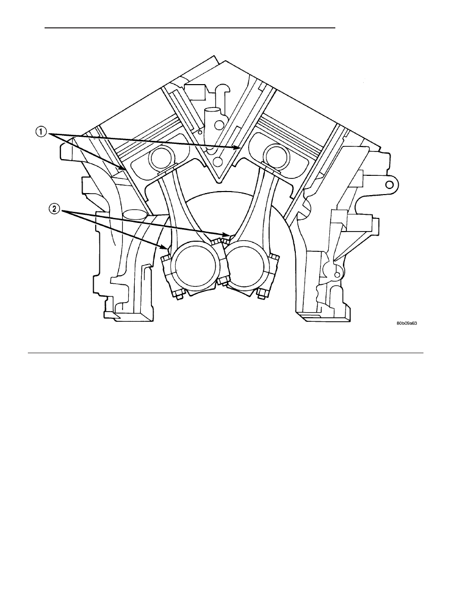
Fig. 82 Piston and Connecting Rod Positioning

1 - MAJOR THRUST SIDE OF PISTON

2 - OIL SQUIRT HOLE

CS

ENGINE 3.8L

9 - 163

CONNECTING ROD BEARINGS (Continued)

(5)

Remove the bearing cap and compare the

width of the flattened Plastigage with the scale pro-
vided on the package (Fig. 83). Locate the band clos-
est to the same width. This band indicates the
amount of oil clearance. Differences in readings
between the ends indicate the amount of taper
present. Record all readings taken. Refer to Engine
Specifications (Refer to 9 - ENGINE - SPECIFICA-
TIONS). Plastigage generally is accompanied by
two scales. One scale is in inches, the other is a
metric scale. If the bearing clearance exceeds
wear limit specification, replace the bearing.

PISTON RINGS

STANDARD PROCEDURE - PISTON RING
FITTING

(1) Wipe cylinder bore clean. Insert the ring and

push down with piston to ensure squareness in bore
to approximately 12 mm (0.50 in.) from top of cylin-
der bore. Check ring gap with a feeler gauge (Fig.
84). For clearance specification (Refer to 9 - ENGINE
- SPECIFICATIONS).

(2) Check piston ring to groove side clearance (Fig.

85). For clearance specification (Refer to 9 - ENGINE
- SPECIFICATIONS)

Fig. 83 Checking Connecting Rod Bearing

Clearance—Typical

Fig. 84 Check Gap on Piston Rings

1 - FEELER GAUGE

Fig. 85 Piston Ring Side Clearance

1 - FEELER GAUGE

9 - 164

ENGINE 3.8L

CS

CONNECTING ROD BEARINGS (Continued)

REMOVAL

(1) Remove piston and connecting rod. (Refer to 9 -

ENGINE/ENGINE BLOCK/PISTON & CONNECT-
ING ROD - REMOVAL)

(2) Remove No. 1 and No.2 piston rings from pis-

ton using a ring expander tool (Fig. 86).

(3) Remove upper oil ring side rail.
(4) Remove lower oil ring side rail.
(5) Remove oil ring expander.

INSTALLATION

(1) Install rings with manufacturers I.D. mark (if

present) facing up, to the top of the piston (Fig. 87).

CAUTION: Install piston rings in the following
order:

1. Oil ring expander.
2. Upper oil ring side rail.
3. Lower oil ring side rail.
4. No. 2 Intermediate piston ring.
5. No. 1 Upper piston ring.
(2)

Install the side rail by placing one end

between the piston ring groove and the expander.
Hold end firmly and press down the portion to be
installed until side rail is in position. Do not use a
piston ring expander 
(Fig. 88).

(3) Install upper side rail first and then the lower

side rail.

(4) Install No. 2 piston ring and then No. 1 piston

ring (Fig. 89).

Fig. 86 Upper and Intermediate Rings - Service

Fig. 87 Piston Ring Installation

1 - NO. 1 PISTON RING
2 - NO. 2 PISTON RING
3 - SIDE RAIL
4 - OIL RING
5 - SPACER EXPANDER

Fig. 88 Installing Side Rail

1 - SIDE RAIL END

Fig. 89 Upper and Intermediate Rings—Installation

CS

ENGINE 3.8L

9 - 165

PISTON RINGS (Continued)

(5) Position piston ring end gaps as shown in (Fig.

90).

(6)

Position oil ring expander gap at least 45°

from the side rail gaps but not on the piston pin cen-
ter or on the thrust direction. Staggering ring gap is
important for oil control.

CRANKSHAFT MAIN
BEARINGS

STANDARD PROCEDURE - MAIN BEARING
FITTING

Bearing caps are not interchangeable and should

be marked at removal to insure correct assembly
(Fig. 91). Upper and lower bearing halves are NOT
interchangeable. Lower main bearing halves of 1, 3
and 4 are interchangeable. Upper main bearing
halves of 1, 3 and 4 are interchangeable.

Upper and lower number 2 bearing halves are

flanged to carry the crankshaft thrust loads and are
NOT interchangeable with any other bearing halves
in the engine (Fig. 92). All bearing cap bolts removed
during service procedures are to be cleaned and
lubricated with engine oil before installation. Bearing
shells are available in standard and the following
undersizes: 0.025 mm (0.001 in.) and 0.254 mm
(0.010 in). Never install an undersize bearing that
will reduce clearance below specifications.

CRANKSHAFT BEARING OIL CLEARANCE

Inspect the crankshaft bearing journals. (Refer to 9

-

ENGINE/ENGINE

BLOCK/CRANKSHAFT

-

INSPECTION)

Engine crankshaft bearing clearances can be deter-

mined by use of Plastigage or the equivalent. The fol-
lowing is the recommended procedures for the use of
Plastigage with the engine in the vehicle or engine
on a repair stand.

PLASTIGAGE METHOD—ENGINE IN-VEHICLE

NOTE: The total clearance of the main bearings can
only be determined with the engine in the vehicle
by removing the weight of the crankshaft. This can
be accomplished by either of two following meth-
ods:

(1) Preferred method:
a. Shim the bearings adjacent to the bearing to be

checked in order to remove the clearance between
upper bearing shell and the crankshaft. This can be
accomplished by placing a minimum of 0.254 mm
(0.010 in.) shim (e. g. cardboard, matchbook cover,
etc.) between the bearing shell and the bearing cap

Fig. 90 Piston Ring End Gap Position

1 - GAP OF LOWER SIDE RAIL
2 - NO. 1 RING GAP
3 - GAP OF UPPER SIDE RAIL
4 - NO. 2 RING GAP AND SPACER EXPANDER GAP

Fig. 91 Main Bearing Cap Identification

Fig. 92 Main Bearing Identification

1 - OIL GROOVES
2 - OIL HOLES
3 - UPPER BEARINGS
4 - LOWER BEARINGS

9 - 166

ENGINE 3.8L

CS

PISTON RINGS (Continued)


Content   ..  700  701  702  703   ..