Chrysler Pacifica. Manual - part 699


  Index      Chrysler     Chrysler Pacifica - service repair manual 2005 year


Search            


Content   ..  697  698  699  700   ..


Chrysler Pacifica. Manual - part 699


(4) For rocker arm disassembly procedures, (Refer

to 9 - ENGINE/CYLINDER HEAD/ROCKER ARMS -
DISASSEMBLY).

DISASSEMBLY - ROCKER ARMS AND SHAFT

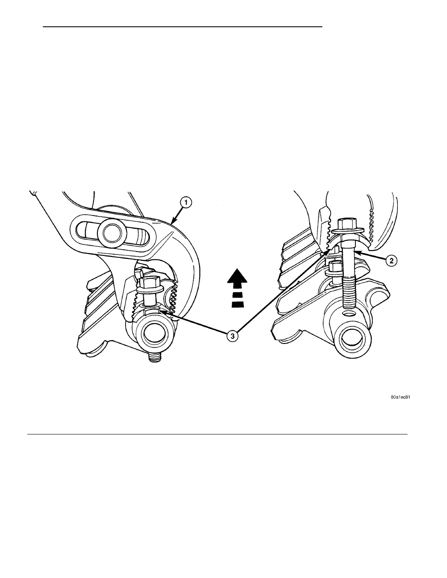
CAUTION: Do not attempt to drive the billeted bolt
from the rocker shaft. This can damage the rocker
arm retainer and bolt assembly.

(1) Remove the rocker arm retainer and bolt by

performing the following procedure:

(a) Using adjustable pliers, grip the edges of the

retainer (Fig. 58).

(b) Apply an upward force with a slight rocking

motion until the retainer disengages from shaft
(Fig. 58).
(2) Remove rocker arms (Fig. 59). Identify the

component locations for reassembly in original loca-
tions.

Fig. 58 ROCKER ARM RETAINER - REMOVAL

1 - ADJUSTABLE PLIERS

3 - ROCKER ARM RETAINER

2 - BILLETED ROCKER SHAFT BOLT

CS

ENGINE 3.8L

9 - 151

ROCKER ARMS (Continued)

ASSEMBLY - ROCKER ARMS AND SHAFT

(1) Install rocker arms on the shaft. Install in the

orginal positions if re-used. Ensure the rocker shaft,
all the retainers and washers are properly positioned
and installed in the correct locations (Fig. 59).

(2) Install rocker arms and shaft to the cylinder

head. (Refer to 9 - ENGINE/CYLINDER HEAD/
ROCKER ARMS - INSTALLATION)

INSTALLATION

ROCKER ARMS AND SHAFT

CAUTION: Ensure the longer shaft retaining bolt is
installed in the proper location on the rocker shaft.
(Refer to 9 - ENGINE/CYLINDER HEAD/ROCKER
ARMS - ASSEMBLY)

(1) Position the rocker arm and shaft assemblies

on the pedestal mounts.

CAUTION: Ensure all pushrods are properly located
on the lifter and the rocker arm socket.

(2) Align each rocker arm socket with each push-

rod end.

CAUTION: The rocker arm shaft should be tight-
ened down slowly, starting with the center bolts.
Allow 20 minutes lifter bleed down time after instal-
lation of the rocker shafts before engine operation.

Fig. 59 ROCKER ARMS AND SHAFT

1 - BOLT (ROCKER SHAFT OIL FEED - LONGER LENGTH)

5 - ROCKER ARM - EXHAUST

2 - SHAFT RETAINER/SPACER - 21.5 mm (0.84 in.)

6 - WASHER

3 -SHAFT RETAINER/SPACER - 37.5 mm (1.47 in.)

7 - ROCKER ARM - INTAKE (LARGER OFFSET)

4 - SHAFT RETAINER/SPACER - 40.9 mm (1.61 in.)

8 - ROCKER ARMS LUBRICATION FEED HOLE (POSITION
UPWARD & TOWARD VALVE SPRING)

Fig. 60 ROCKER ARMS AND SHAFT

1 - ROCKER ARMS AND SHAFT ASSEMBLY
2 - ROCKER SHAFT BOLTS

9 - 152

ENGINE 3.8L

CS

ROCKER ARMS (Continued)

(3) Slowly tighten rocker shaft bolts evenly until

shaft is seated. Tighten bolts to 23 N·m (200 in. lbs.)
(Fig. 60).

(4) Install the cylinder head cover(s). (Refer to 9 -

ENGINE/CYLINDER

HEAD/CYLINDER

HEAD

COVER(S) - INSTALLATION.)

VALVE STEM SEALS

DESCRIPTION

The valve stem seals are made of Viton rubber. The

seals are positioned over the valve stem and seated
on the valve guide (Fig. 61).

REMOVAL

(1) Remove the valve springs. (Refer to 9 -

ENGINE/CYLINDER

HEAD/VALVE

SPRINGS

-

REMOVAL)

(2) Remove the valve stem seal (Fig. 61).

INSTALLATION

(1) Install the valve stem seal squarely over the

valve guide, using the valve stem as a guide (Fig.
61). Do not force the seal against top of the valve
guide.

(2) Install the valve spring. (Refer to 9 - ENGINE/

CYLINDER HEAD/VALVE SPRINGS - INSTALLA-
TION)

ENGINE BLOCK

DESCRIPTION

The cylinder block is made of cast iron and is a

deep skirt design.

STANDARD PROCEDURE - CYLINDER BORE
HONING

(1) Used carefully, the cylinder bore resizing hone,

recommended tool C-823 or equivalent, equipped
with 220 grit stones, is the best tool for this honing
procedure. In addition to deglazing, it will reduce
taper and out-of-round as well as removing light
scuffing, scoring or scratches. Usually a few strokes
will clean up a bore and maintain the required lim-
its.

(2) Deglazing of the cylinder walls may be done

using a cylinder surfacing hone, recommended tool
C-3501 or equivalent, equipped with 280 grit stones,
if the cylinder bore is straight and round. 20–60
strokes depending on the bore condition, will be suf-
ficient to provide a satisfactory surface. Use a light
honing oil. Do not use engine or transmission oil,
mineral spirits or kerosene. 
Inspect cylinder walls
after each 20 strokes.

(3) Honing should be done by moving the hone up

and down fast enough to get a cross-hatch pattern.
When hone marks intersect at 40-60 degrees, the
cross hatch angle is most satisfactory for proper seat-
ing of rings (Fig. 62).

(4)

A controlled

hone

motor

speed

between

200–300 RPM is necessary to obtain the proper cross-
hatch angle. The number of up and down strokes per
minute can be regulated to get the desired 40–60
degree angle. Faster up and down strokes increase
the cross-hatch angle.

(5) After honing, it is necessary that the block be

cleaned again to remove all traces of abrasive.

Fig. 61 VALVE STEM SEAL

Fig. 62 Cylinder Bore Cross-Hatch Pattern

1 - CROSS-HATCH PATTERN
2 - 40°–60°

CS

ENGINE 3.8L

9 - 153

ROCKER ARMS (Continued)

CAUTION: Ensure all abrasives are removed from
engine parts after honing. It is recommended that a
solution of soap and hot water be used with a
brush and the parts then thoroughly dried. The bore
can be considered clean when it can be wiped
clean with a white cloth and cloth remains clean.
Oil the bores after cleaning to prevent rusting.

CLEANING

Clean cylinder block thoroughly using a suitable

cleaning solvent.

INSPECTION

ENGINE BLOCK

(1) Clean cylinder block thoroughly and check all

core hole plugs for evidence of leaking.

(2) If new core plugs are to be installed, (Refer to 9

- ENGINE - STANDARD PROCEDURE - ENGINE
CORE AND OIL GALLERY PLUGS).

(3) Examine block and cylinder bores for cracks or

fractures.

(4) Check block deck surfaces for flatness. Deck

surface must be within service limit of 0.1 mm (0.004
in.).

CYLINDER BORE

NOTE: The cylinder bores should be measured at
normal room temperature, 21°C (70°F).

The cylinder walls should be checked for out-of-

round and taper with Tool C119 or equivalent (Fig.

63) (Refer to 9 - ENGINE - SPECIFICATIONS). If
the cylinder walls are badly scuffed or scored, the
cylinder block should be replaced, and new pistons
and rings fitted.

Measure the cylinder bore at three levels in direc-

tions A and B (Fig. 63). Top measurement should be
10 mm (3/8 in.) down and bottom measurement
should be 10 mm (3/8 in.) up from bottom of bore.
(Refer to 9 - ENGINE - SPECIFICATIONS).

HYDRAULIC LIFTERS (CAM IN
BLOCK)

DESCRIPTION

The hydraulic lifters are a roller type design and

are positioned in the cylinder block with the lubrica-
tion whole facing upward. The lifters are aligned and
retained by a yoke and a retainer (Fig. 64).

Fig. 63 Cylinder Bore Measurement

Fig. 64 HYDRAULIC LIFTERS

1 - YOKE RETAINER
2 - BOLT - YOKE RETAINER
3 - ALIGNING YOKE
4 - HYDRAULIC LIFTER

9 - 154

ENGINE 3.8L

CS

ENGINE BLOCK (Continued)


Content   ..  697  698  699  700   ..