Chrysler Pacifica. Manual - part 670


  Index      Chrysler     Chrysler Pacifica - service repair manual 2005 year


Search            


Content   ..  668  669  670  671   ..


Chrysler Pacifica. Manual - part 670


(8) Install camshaft sprocket. Counterhold the

camshaft sprocket gear and tighten the camshaft
sprocket bolt to 102 N·m plus a 1/4 turn (75 lbs. ft.
plus a 1/4 turn). (Refer to 9 - ENGINE/VALVE TIM-
ING/TIMING BELT/CHAIN AND SPROCKETS -
INSTALLATION).

(9) Install the rear camshaft thrust plate.
(10) Rotate the camshaft gear to it’s alignment

mark and check the left camshaft gear and crank-
shaft gear timing alignment marks.

(11) Install the timing belt and tensioner (Refer to

9 - ENGINE/VALVE TIMING/TIMING BELT/CHAIN
AND SPROCKETS - INSTALLATION).

(12) Install the timing belt outer cover (Refer to 9 -

ENGINE/VALVE TIMING/TIMING BELT / CHAIN
COVER(S) - INSTALLATION).

(13) Install the power steering reservoir.
(14) Install the vibration damper (Refer to 9 -

ENGINE/ENGINE BLOCK/VIBRATION DAMPER -
INSTALLATION).

(15) Install the upper engine mount (Refer to 9 -

ENGINE/ENGINE MOUNTING/FRONT MOUNT -
INSTALLATION).

(16) Install the accessory drive belt tensioner.
(17) Install the accessory drive belt idler pulley.
(18) Install the right exhaust manifold (Refer to 9

- ENGINE/MANIFOLDS/EXHAUST MANIFOLD -
INSTALLATION).

(19) Install the exhaust cross over pipe (Refer to 9

- ENGINE/MANIFOLDS/EXHAUST MANIFOLD -
INSTALLATION).

(20) Install the catalytic converter and exhaust

system.

(21) Connect both oxygen sensors.
(22) Lower the vehicle.
(23) Install the right rocker arm assembly.
(24) Install the right cylinder head cover and

ground strap.

(25) Install lower intake manifold (Refer to 9 -

ENGINE/MANIFOLDS/INTAKE

MANIFOLD

-

INSTALLATION).

(26) Install the fuel rail.
(27) Install the upper intake manifold (Refer to 9 -

ENGINE/MANIFOLDS/INTAKE

MANIFOLD

-

INSTALLATION).

(28) Install the air cleaner element housing (Refer

to

9

-

ENGINE/AIR

INTAKE

SYSTEM/AIR

CLEANER HOUSING - INSTALLATION)..

(29) Install the engine cover.
(30) Fill the coolant system.
(31) Connect the negative battery cable.

LEFT CYLINDER HEAD

CAUTION: THE CYLINDER HEAD GASKETS ARE
NOT

INTERCHANGEABLE

BETWEEN

CYLINDER

HEADS AND ARE CLEARLY MARKED RIGHT OR
LEFT.

The cylinder head bolts are tightened using a

torque plus angle procedure. The bolts must be
examined BEFORE reuse. If the threads are
necked down the bolts must be replaced (Fig.
24).
.

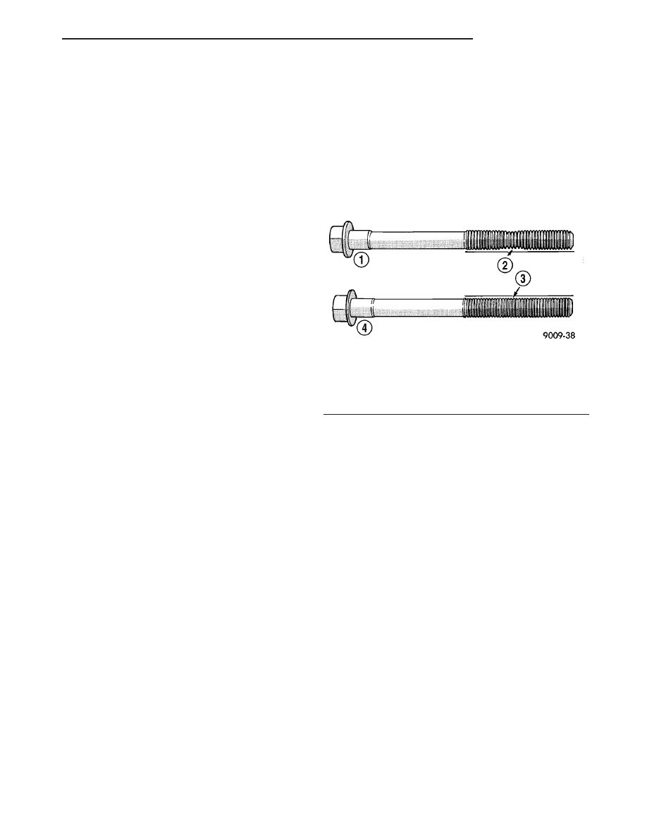
Necking can be checked by holding a scale or

straight edge against the threads. If all the threads
do not contact the scale the bolt must be replaced
(Fig. 26).

CAUTION: When cleaning cylinder head and cylin-
der block surfaces, DO NOT use a metal scraper
because the surfaces could be cut or ground. Use
ONLY a wooden or plastic scraper (Refer to 9 -
ENGINE - STANDARD PROCEDURE - ENGINE GAS-
KET SURFACE PREPARATION).

(1) Clean sealing surfaces of cylinder head and

block.

CAUTION: Ensure that the correct head gaskets are
used and are oriented correctly on cylinder block.

(2) Install

head

gasket

over

locating

dowels.

Ensure the gasket is installed on the correct side of
engine.

NOTE: Before installing the cylinder head bolts,
lubricate the threads with engine oil.

(3) Install the cylinder head over locating dowels,

insert and finger tighten the head bolts.

(4) Tighten the cylinder head bolts in the sequence

shown in (Fig. 27). Using the 4 step torque-turn
method, tighten according to the following torque val-
ues:

• Step 1: All to 61 N·m (45 ft. lbs.)

• Step 2: All to 88 N·m (65 ft. lbs.)

• Step 3: All (again) to 88 N·m (65 ft. lbs.)

Fig. 26 Check for Stretched Bolts

1 - STRETCHED BOLT
2 - THREADS ARE NOT STRAIGHT ON LINE
3 - THREADS ARE STRAIGHT ON LINE
4 - UNSTRETCHED BOLT

CS

ENGINE 3.5L

9 - 35

CYLINDER HEAD(S) (Continued)

• Step 4: + 90° Turn Do not use a torque

wrench for this step.

(5) Bolt torque after 90° turn should be over 122

N·m (90 ft. lbs.) in the tightening direction. If not,
replace the bolt.

(6) Install the inner timing cover to cylinder head

bolts. Tighten bolts to 54 N·m (40 lbs.ft.).

(7) Install camshaft sprocket. Counterhold the

camshaft sprocket gear and tighten the camshaft
sprocket bolt to 115 N·m plus a 1/4 turn (85 lbs. ft.
plus a 1/4 turn). (Refer to 9 - ENGINE/VALVE TIM-
ING/TIMING BELT/CHAIN AND SPROCKETS -
INSTALLATION).

(8) Install the rear camshaft thrust plate.
(9) Rotate the camshaft gear to it’s alignment

mark and check the right camshaft gear and crank-
shaft gear timing alignment marks.

(10) Install the timing belt and tensioner (Refer to

9 - ENGINE/VALVE TIMING/TIMING BELT/CHAIN
AND SPROCKETS - INSTALLATION).

(11) Install the timing belt front cover (Refer to 9 -

ENGINE/VALVE TIMING/TIMING BELT / CHAIN
COVER(S) - INSTALLATION).

(12) Install the vibration damper (Refer to 9 -

ENGINE/ENGINE BLOCK/VIBRATION DAMPER -
INSTALLATION).

(13) Install the upper engine mount (Refer to 9 -

ENGINE/ENGINE MOUNTING/FRONT MOUNT -
INSTALLATION).

(14) Install the accessory drive belt tensioner.
(15) Install the accessory drive belt idler pulley.
(16) Install the left exhaust manifold (Refer to 9 -

ENGINE/MANIFOLDS/EXHAUST

MANIFOLD

-

INSTALLATION).

(17) Install the exhaust cross over pipe (Refer to 9

- ENGINE/MANIFOLDS/EXHAUST MANIFOLD -
INSTALLATION).

(18) Install the left rocker arm assembly.
(19) Install the left cylinder head cover and ground

strap.

(20) Install lower intake manifold (Refer to 9 -

ENGINE/MANIFOLDS/INTAKE

MANIFOLD

-

INSTALLATION).

(21) Install the fuel rail.
(22) Install the upper intake manifold (Refer to 9 -

ENGINE/MANIFOLDS/INTAKE

MANIFOLD

-

INSTALLATION).

(23) Install the radiator cooling fan assembly

(Refer to 7 - COOLING/ENGINE/RADIATOR FAN -
INSTALLATION).

(24) Install the radiator core support.
(25) Install the radiator close out panel.
(26) Install the air cleaner element housing (Refer

to

9

-

ENGINE/AIR

INTAKE

SYSTEM/AIR

CLEANER HOUSING - INSTALLATION).

(27) Install the engine cover.
(28) Fill the coolant system.
(29) Connect the negative battery cable.

SEAL -CAMSHAFT OIL

REMOVAL

RIGHT CYLINDER HEAD

(1) Disconnect the negative battery cable.
(2) Remove front timing cover and align the cam-

shaft gear and crankshaft gear timing marks to TDC
(Refer to 9 - ENGINE/VALVE TIMING/TIMING
BELT / CHAIN COVER(S) - REMOVAL).

(3) Remove

timing

belt

and

right

camshaft

sprocket (Refer to 9 - ENGINE/VALVE TIMING/TIM-
ING BELT/CHAIN AND SPROCKETS - REMOVAL).

(4) Remove the camshaft thrust plate from the

rear of the cylinder head.

(5) Remove the cylinder head cover (Refer to 9 -

ENGINE/CYLINDER

HEAD/CYLINDER

HEAD

COVER(S) - REMOVAL).

(6) Remove the rocker arm assembly (Refer to 9 -

ENGINE/CYLINDER

HEAD/ROCKER

ARM

/

ADJUSTER ASSY - REMOVAL).

(7) Maneuver the camshaft rearward and out of

the cylinder head approximately 3.5 inches (Fig. 28).

NOTE: Care must be taken not to damage the cylin-
der head to seal or camshaft journal surfaces when
removing the camshaft seal.

(8) Using an appropriate driver carefully remove

camshaft oil seal (Fig. 28).

LEFT CYLINDER HEAD

(1) Disconnect the negative battery cable.
(2) Drain cooling system.
(3) Remove front timing cover and align the cam-

shaft gear and crankshaft gear timing marks to TDC
(Refer to 9 - ENGINE/VALVE TIMING/TIMING
BELT / CHAIN COVER(S) - REMOVAL).

Fig. 27 Cylinder Head Bolt Tightening Sequence

9 - 36

ENGINE 3.5L

CS

CYLINDER HEAD(S) (Continued)

(4) Remove the rear timing cover (Refer to 9 -

ENGINE/VALVE TIMING/TIMING BELT / CHAIN
COVER(S) - REMOVAL).

(5) Remove the cylinder head cover (Refer to 9 -

ENGINE/CYLINDER

HEAD/CYLINDER

HEAD

COVER(S) - REMOVAL).

(6) Remove the rocker arm assembly (Refer to 9 -

ENGINE/CYLINDER

HEAD/ROCKER

ARM

/

ADJUSTER ASSY - REMOVAL).

(7) Remove the camshaft thrust plate from the

rear of the cylinder head.

(8) Maneuver the camshaft rearward and out of

the cylinder head approximately 3.5 inches (Fig. 29)

NOTE: Care must be taken not to damage the cylin-
der head to seal or camshaft journal surfaces when
removing the camshaft seal.

(9) Using an appropriate driver carefully remove

camshaft oil seal (Fig. 29).

INSTALLATION

RIGHT CYLINDER HEAD

(1) Position the camshaft seal into the cylinder

head (Fig. 30).

(2) Using special tool MD-998306 tap the seal into

place (Fig. 30).

(3) Apply light coat of clean engine oil to the cam-

shaft oil seal lip and Special Tool 6788 Seal Protector
Sleeve.

Fig. 28 CAMSHAFT SEAL REMOVAL - RIGHT

CYLINDER HEAD

1 - CYLINDER HEAD
2 - DRIFT
3 - CAMSHAFT

Fig. 29 CAMSHAFT SEAL REMOVAL - LEFT

CYLINDER HEAD

1 - DRIFT
2 - CAMSHAFT
3 - CYLINDER HEAD

Fig. 30 CAMSHAFT SEAL INSTALLATION

1 - REAR TIMING COVER
2 - SPECIAL TOOL 6788

CS

ENGINE 3.5L

9 - 37

SEAL -CAMSHAFT OIL (Continued)

(4) Install oil seal Special Tool 6788 Seal Protector

Sleeve onto the camshaft (Fig. 31).

(5) Slide the camshaft forward, inserting the seal

protector through the camshaft seal until the cam-
shaft seats (Fig. 31).

(6) Remove Special Tool 6788 from the camshaft.
(7) Install the camshaft thrust plate to the rear of

the cylinder head.

(8) Install camshaft sprocket and timing belt

(Refer to 9 - ENGINE/VALVE TIMING/TIMING
BELT/CHAIN

AND

SPROCKETS

-

INSTALLA-

TION).

LEFT CYLINDER HEAD

(1) Position the camshaft seal into the cylinder

head

(2) Using special tool MD-998306 tap the seal into

place (Fig. 32).

(3) Apply light coat of engine oil to the camshaft

oil seal lip and Special Tool 6788 Seal Protector
Sleeve.

(4) Install oil seal Special Tool 6788 Seal Protector

Sleeve onto the camshaft (Fig. 33)

(5) Slide the camshaft forward, inserting the seal

protector through the camshaft seal until the cam-
shaft seats (Fig. 33).

(6) Remove Special Tool 6788 from the camshaft.
(7) Install the camshaft thrust plate to the rear of

the cylinder head.

(8) Install rear timing belt cover (Refer to 9 -

ENGINE/VALVE TIMING/TIMING BELT / CHAIN
COVER(S) - INSTALLATION).

Fig. 31 CAMSHAFT INSTALLATION

1 - REAR TIMING COVER
2 - SPECIAL TOOL 6788
3 - CAMSHAFT

Fig. 32 CAMSHAFT SEAL

1 - MALLET
2 - SPECIAL TOOL MD-998306
3 - CYLINDER HEAD

Fig. 33 CAMSHAFT INSTALLATION - LEFT

1 - CAMSHAFT
2 - SPECIAL TOOL6788
3 - CAMSHAFT SEAL
4 - CYLINDER HEAD

9 - 38

ENGINE 3.5L

CS

SEAL -CAMSHAFT OIL (Continued)


Content   ..  668  669  670  671   ..