Chrysler Pacifica. Manual - part 431
DIAGNOSIS AND TESTING - SUSPENSION AND
STEERING
CONDITION
POSSIBLE CAUSES
CORRECTION
Front End Whine On Turns
1. Defective wheel bearing
1. Replace hub and bearing
2. Incorrect wheel alignment
2. Check and reset wheel alignment
3. Worn tires
3. Replace tires
Front End Growl Or
Grinding On Turns
1. Defective wheel bearing
1. Replace hub and bearing
2. Engine mount grounding
2. Check for motor mount hitting frame
rail and reposition engine as required
3. Worn or broken C/V joint
3. Replace C/V joint
4. Loose wheel lug nuts
4. Verify wheel lug nut torque
5. Incorrect wheel alignment
5. Check and reset wheel alignment
6. Worn tires
6. Replace tires
7. Front strut pin in upper strut mount
7. Replace the front strut upper mount
and bearing
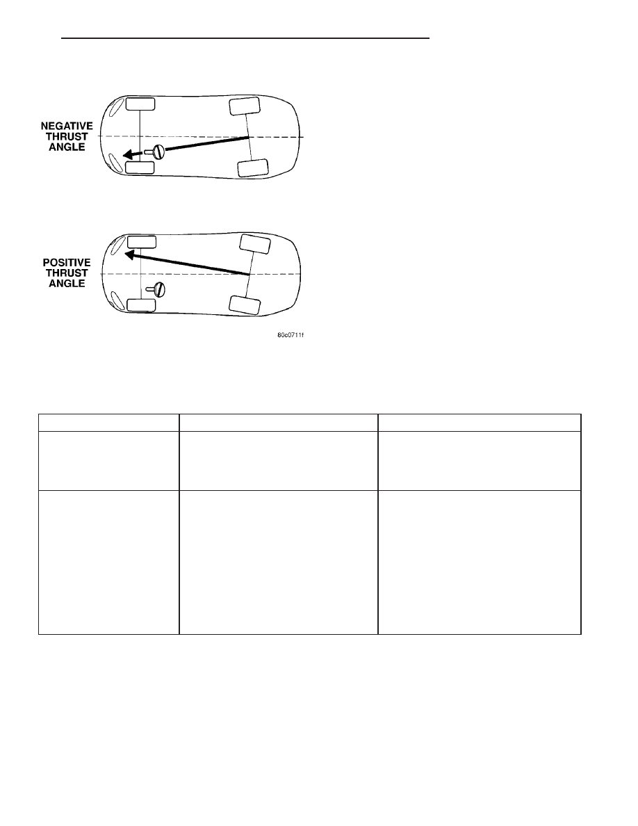
Fig. 6 Thrust Angle
CS
WHEEL ALIGNMENT
2 - 41
WHEEL ALIGNMENT (Continued)