Chrysler Stratus Convertible. Manual - part 388


  Index      Chrysler     Chrysler Stratus Convertible - service repair manual 1995-2000 year


Search            


Content   ..  386  387  388  389   ..


Chrysler Stratus Convertible. Manual - part 388


(18) Install battery tray and battery. Set Power-

train Control Module (PCM) into place.

(19) Install air cleaner and hoses.
(20) Evacuate and charge air conditioning system.

Refer to Group 24, Heating and Air Conditioning for
procedures.

(21) Install oil filter. Fill engine crankcase with

proper oil to correct level.

(22) Start engine and run until operating temper-

ature is reached.

(23) Adjust transmission linkage, if necessary.

INTAKE MANIFOLD

FUEL SYSTEM PRESSURE RELEASE PROCEDURE

WARNING: RELEASE FUEL SYSTEM PRESSURE
BEFORE SERVICING SYSTEM COMPONENTS. SER-
VICE VEHICLES IN WELL VENTILATED AREAS AND
AVOID IGNITION SOURCES. NEVER SMOKE WHILE
SERVICING THE VEHICLE.

To release fuel pressure, refer to Group 14, Fuel

System for procedure.

REMOVAL

(1) Perform fuel system pressure release procedure

before attempting any repairs.
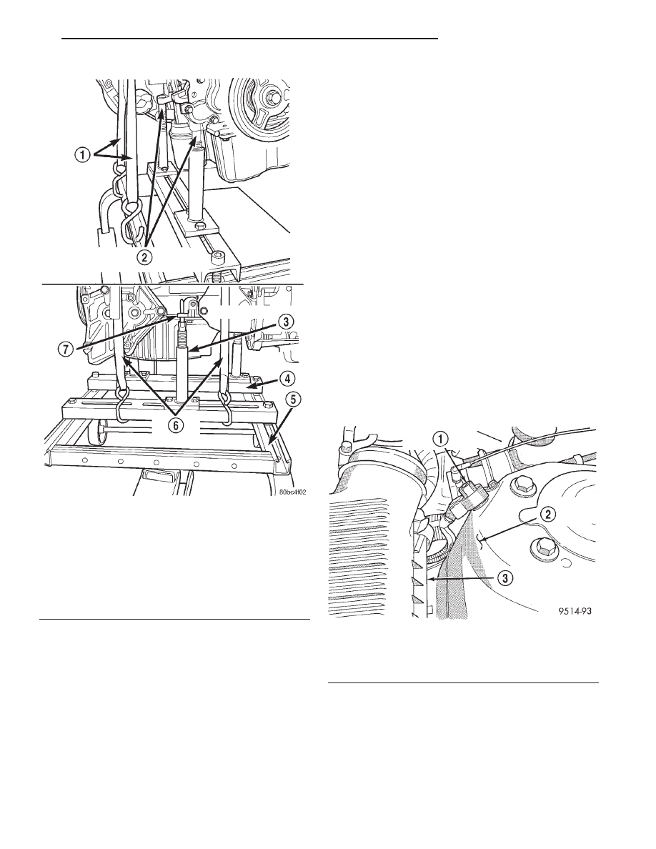
(2) Disconnect

negative

cable

from

auxiliary

jumper terminal (Fig. 32).

(3) Remove air inlet resonator. Refer to Group 14,

Fuel System for procedure.

(4) Perform fuel system pressure relief procedure

and disconnect the fuel supply line quick connect at
the fuel rail assembly. Refer to Group 14, Fuel Sys-
tem for procedure.

WARNING: WRAP SHOP TOWELS AROUND HOSE
TO CATCH ANY GASOLINE SPILLAGE.

(5) Remove fuel rail assembly attaching screws

and remove fuel rail assembly from engine. Cover
injector holes with a suitable covering.

CAUTION: Do not set fuel injectors on their tips,
damage may occur to the injectors

Fig. 31 Positioning Engine Cradle Support Post

Mounts

1 – SAFETY STRAPS
2 – PLACE REAR POSTS INTO LOCATING HOLES
3 – SPECIAL TOOL 6848
4 – SPECIAL TOOL 6710
5 – SPECIAL TOOL 6135
6 – SAFETY STRAPS
7 – PLACE FRONT POST UNDER BLOCK FLANGE

Fig. 32 Auxiliary Jumper Terminal

1 – AUXILIARY JUMPER TERMINAL
2 – LEFT STRUT TOWER
3 – AIR CLEANER HOUSING

JX

2.0L SOHC ENGINE

9 - 25

REMOVAL AND INSTALLATION (Continued)

(6) Remove accelerator and speed control cables

from throttle lever and bracket. Refer to Group 14,
Fuel System for procedures.

(7) Disconnect idle air control (IAC) motor and

throttle position sensor (TPS) wiring connectors (Fig.
33).

(8) Disconnect intake air temperature electrical

connector (Fig. 34).

(9) Disconnect leak detection pump and PCV

hoses.

(10) Disconnect knock sensor electrical connector

and disconnect wiring harness from tab located on
the intake manifold (Fig. 34).

(11) Remove transaxle to throttle body support

bracket fasteners at the throttle body and loosen the
fastener at the transaxle end.

(12) Remove EGR tube bolts at the valve and at

the intake manifold (Fig. 35). Remove tube from
engine and discard gaskets.

(13) Remove the intake manifold to inlet water

tube support fastener (Fig. 36).

(14) Remove intake manifold fasteners and washer

assemblies. Remove intake manifold.

INSTALLATION

Replace all O-ring seals (Fig. 37). All intake mani-

fold fasteners and washers are to be discarded and
replaced with NEW fasteners and washers.

(1) Install

new

intake

manifold

O-ring

seals.

Tighten fasteners to 12 N·m (105 in. lbs.) in sequence
shown in (Fig. 36).

(2) Remove covering from fuel injector holes and

insure the holes are clean. Install fuel rail assembly

to intake manifold. Tighten screws to 23 N·m (200 in.
lbs.).

(3) Connect PCV and brake booster hoses.
(4) Inspect quick connect fittings for damage,

replace if necessary. Refer to Group 14, Fuel System
for procedure. Lubricate tube with clean engine oil.
Connect fuel supply hose to fuel rail assembly. Check
connection by pulling on connector to insure it locked
into position.

(5) Install throttle body. Tighten fasteners to 22

N·m (200 in. lbs.). Install transaxle to throttle body
support bracket and tighten to 12 N·m (105 in. lbs.)

Fig. 33 Idle Air Control (IAC) Motor, Throttle

Position Sensor (TPS) Wiring Connectors, and

Vacuum Hose Connection.

1 – IDLE AIR CONTROL MOTOR
2 – THROTTLE POSITION SENSOR

Fig. 34 Intake Manifold Electrical Connectors and

Vacuum Hose Connections

1 – MAP SENSOR
2 – INTAKE AIR TEMPERATURE SENSOR
3 – VAPOR HOSE CONNECTION
4 – KNOCK SENSOR
5 – BRAKE BOOSTER HOSE CONNECTION

Fig. 35 Tube Assembly—Typical

1 – EGR TUBE TO INTAKE MANIFOLD FASTENERS
2 – EGR VALVE TO TUBE FASTENERS

9 - 26

2.0L SOHC ENGINE

JX

REMOVAL AND INSTALLATION (Continued)

at the throttle body first. Next tighten the bracket at
the transaxle.

(6) Connect manifold absolute pressure (MAP) and

intake air temperature sensor wiring connectors.

(7) Connect knock sensor electrical and starter

relay connectors. Connect wiring harness to intake
manifold tab.

(8) Connect Idle Air Control (IAC) motor and

Throttle Position Sensor (TPS) wiring connectors.

(9) Connect vacuum hoses to throttle body.
(10) Install accelerator and speed control cables to

their bracket and connect them to the throttle lever.
Refer to Group 14, Fuel System Throttle Body Instal-
lation procedure.

(11) With new EGR gaskets in position, loosely

assemble the EGR tube onto valve and intake mani-
fold finger tight. Tighten tube fasteners at the EGR

valve first to 11 N·m (95 in. lbs.). Then, tighten the
intake manifold side fasteners to 11 N·m (95 in. lbs.).

(12) Connect negative cable to auxiliary jumper

terminal.

(13) With the DRB scan tool use ASD Fuel System

Test to pressurize system to check for leaks.

CAUTION: When using the ASD Fuel System Test,
the Auto Shutdown (ASD) relay will remain ener-
gized for 7 minutes or until the ignition switch is
turned to the OFF position, or Stop All Test is
selected.

EXHAUST MANIFOLD

REMOVAL

(1) Disconnect exhaust pipe from manifold.
(2) Remove the entire exhaust system. Refer to

Group 11, Exhaust System for procedure.

(3) Remove exhaust manifold heat shield (Fig. 38).
(4) Disconnect oxygen sensor electrical connector.
(5) Remove exhaust manifold retaining fasteners

and remove exhaust manifold (Fig. 39).

(6) Remove and discard manifold gasket.

INSTALLATION

(1) Install new manifold gasket. DO NOT APPLY

SEALER.

(2) Position exhaust manifold in place. Tighten fas-

teners, starting at center and progressing outward in
both directions to 23 N·m (200 in. lbs.). Repeat this
procedure until all fasteners are at specified torque.

(3) Connect oxygen sensor electrical connector.
(4) Install exhaust manifold heat shield.
(5) Install exhaust system. Refer to Group 11,

Exhaust System for procedure.

(6) Attach exhaust pipe with gasket to the mani-

fold and tighten fasteners to 28 N·m (250 in. lbs.).

Fig. 36 Intake Manifold Tightening Sequence

1 – INTAKE MANIFOLD TO WATER INLET SUPPORT

Fig. 37 Intake Manifold O-Rings

1 – THROTTLE BODY TO MANIFOLD GASKET
2 – INJECTOR RAIL MOUNTS
3 – CAPTIVE O-RING GASKET

Fig. 38 Exhaust Manifold Heat Shield

1 – HEAT SHIELD ATTACHING SCREWS

JX

2.0L SOHC ENGINE

9 - 27

REMOVAL AND INSTALLATION (Continued)

CYLINDER HEAD COVER

REMOVAL

(1) Disconnect make-up air (Fig. 40) and PCV (Fig.

41) hoses from cylinder head cover.

(2) Remove ignition coil and spark plug cables

(Fig. 42).

(3) Remove cylinder head cover bolts.
(4) Remove cylinder head cover.

INSTALLATION

(1) Clean gasket surfaces. Inspect gasket and seals

(Fig. 43). Replace as necessary. For replacement of
spark plug tube seals, refer to Spark Plug Tube Seals
in this section for procedure.

CAUTION: Do not attempt to loosen or remove baf-
fle plate attaching screws. The screws are self-tap-
ping, and in the attempt to retighten, thread damage
(stripping) will result.

(2) Install cylinder head cover and gasket. Tighten

bolts to 12 N·m (105 in. lbs.).

(3) Install ignition coil and spark plug cables (Fig.

42). Tighten ignition coil fasteners to 12 N·m (105 in.
lbs.).

(4) Connect make-up air (Fig. 40) and PCV (Fig.

41) hoses.

Fig. 39 Exhaust Manifold

1 – HEATED OXYGEN SENSOR

Fig. 40 Make-Up Air Hose

Fig. 41 PCV Valve Hose

Fig. 42 Ignition Coil and Spark Plug Cables

1 – IGNITION COILS
2 – SPARK PLUG CABLE
3 – SPARK PLUG INSULATOR

9 - 28

2.0L SOHC ENGINE

JX

REMOVAL AND INSTALLATION (Continued)


Content   ..  386  387  388  389   ..