Chrysler Stratus Convertible. Manual - part 221


  Index      Chrysler     Chrysler Stratus Convertible - service repair manual 1995-2000 year


Search            


Content   ..  219  220  221  222   ..


Chrysler Stratus Convertible. Manual - part 221


over) of propylene-glycol is 125 deg. C (257 deg. F )
at 96.5 kPa (14 psi), compared to 128 deg. C (263
deg. F) for ethylene-glycol. Use of propylene-glycol
can result in boil-over or freeze-up on a cooling sys-
tem designed for ethylene-glycol. Propylene glycol
also has poorer heat transfer characteristics than
ethylene glycol. This can increase cylinder head tem-
peratures under certain conditions.

Propylene-glycol/ethylene-glycol

Mixtures

can

cause the destabilization of various corrosion inhibi-
tors, causing damage to the various cooling system
components. Also, once ethylene-glycol and propy-
lene-glycol based coolants are mixed in the vehicle,
conventional methods of determining freeze point will
not be accurate. Both the refractive index and spe-
cific gravity differ between ethylene glycol and propy-
lene glycol.

OPERATION

ETHYLENE-GLYCOL MIXTURES

Coolant flows through the engine block absorbing

the heat from the engine, then flows to the radiator
where the cooling fins in the radiator transfers the
heat from the coolant to the atmosphere. During cold
weather the ethylene-glycol coolant prevents water
present in the cooling system from freezing within
temperatures indicated by mixture ratio of coolant to
water.

ENGINE THERMOSTAT—2.0L ENGINE

DESCRIPTION

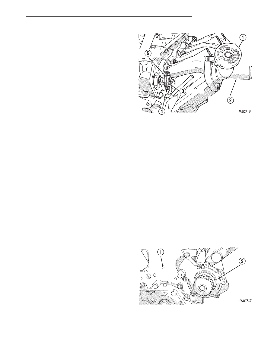
The 2.0L engine thermostat is located on the front

of the engine (radiator side) in the thermostat hous-
ing/engine outlet connector (Fig. 2). The thermostat
has a air bleed vent located in the flange and a
O-ring with a locating dimple incorporate on it.
There is a relief in the housing for positioning the air
bleed.

OPERATION

The engine cooling thermostat is a wax pellet

driven, reverse poppet choke type. The thermostat is
designed to provide the fastest warm up possible by
preventing leakage through it and to guarantee a
minimum engine operating temperature of 88 to
93°C (192 to 199°F). The thermostat also will auto-
matically reach wide open so it will not restrict flow
to the radiator as temperature of the coolant rises in
hot weather to around 104°C (220°F). Above this
temperature the coolant temperature is controlled by
the radiator, fan, and ambient temperature, not the
thermostat.

The thermostat is operated by a wax filled con-

tainer (pellet) which is sealed. When heated coolant

reaches

a

predetermined

temperature,

the

wax

expands enough to overcome the closing spring and
water pump pressure, which forces the valve to open.

Coolant leakage into the wax pellet will cause a

thermostat to fail open. Do not attempt to free-up a
stuck open thermostat.

WATER PUMP—2.0L ENGINE

DESCRIPTION

The water pump has a diecast aluminum body and

housing with a stamped steel impeller. The water
pump bolts directly to the block (Fig. 3) and is driven
by the timing belt. Cylinder block to water pump
sealing is provided by a rubber O-ring.

Fig. 2 Thermostat/Engine Outlet Connector—2.0L

Engine

1 – PRESSURE CAP
2 – THERMOSTAT HOUSING/ENGINE OUTLET CONNECTOR
3 – THERMOSTAT
4 – O-RING
5 – VENT FACING UP

Fig. 3 Water Pump

1 – CYLINDER BLOCK
2 – PUMP BODY

JX

COOLING SYSTEM

7 - 3

DESCRIPTION AND OPERATION (Continued)

OPERATION

The water pump is the heart of the cooling system.

The coolant is pumped through the engine block, cyl-
inder head, heater core, and radiator.

COOLANT RECOVERY SYSTEM

DESCRIPTION

The coolant recovery system consist of a container

and hose that is connected to the cooling system.

OPERATION

This system works in conjunction with the pres-

sure cap to utilize thermal expansion and contraction
of the coolant to keep the coolant free of trapped air.
It provides a volume for expansion and contraction,
provides a convenient and safe method for checking
coolant level, and adjusting level at atmospheric
pressure without removing the pressure cap. It also
provides some reserve coolant to cover minor leaks
and evaporation or boiling losses. All vehicles are
equipped with this system.

HOSE CLAMPS

DESCRIPTION

The cooling system utilizes both worm drive and

spring type hose clamps. If a spring type clamp
replacement is necessary, replace with the original
Mopar

t equipment spring type clamp.

CAUTION: A number or letter is stamped into the
tongue of constant tension clamps. If replacement
is necessary, use only a original equipment clamp
with matching number or letter (Fig. 4).

OPERATION

The worm type hose clamp uses a specified torque

value to maintain proper tension on a hose connec-
tion.

The spring type hose clamp applies constant ten-

sion on a hose connection. To remove a spring type
hose clamp, only use constant tension clamp pliers
designed to compress the hose clamp.

ENGINE BLOCK HEATER

DESCRIPTION

The block heater is operated by ordinary house

current (110 Volt A.C.) through a power cord and con-
nector behind the radiator grille. The heater is
mounted in a core hole (in place of a core hole plug)
in the engine block, with the heating element
immersed in coolant.

CAUTION: The power cord must be secured in its
retainer clips, and not positioned so it could con-
tact linkages or exhaust manifolds and become
damaged.

OPERATION

The block heater element is submerged in the cool-

ing system’s coolant. When electrical power (110 volt
A.C.) is applied to the element, it creates heat. This
heat is transferred to the engine coolant. This pro-
vides easier engine starting and faster warm-up
when vehicle is operated in areas having extremely
low temperatures.

RADIATOR

DESCRIPTION

The radiator is a cross flow type (horizontal tubes)

with design features that provide greater strength as
well as sufficient heat transfer capabilities to keep
the engine coolant within operating temperatures.
The radiator cooling tubes are made of aluminum
and the side tanks are plastic (Fig. 5).

OPERATION

The radiator functions as a heat exchanger, using

air flow across the exterior of the radiator tubes. This
heat is then transferred from the coolant and into
the passing air.

Fig. 4 Spring Clamp Size Location

1 – SPRING CLAMP SIZE LOCATION

7 - 4

COOLING SYSTEM

JX

DESCRIPTION AND OPERATION (Continued)

COOLING SYSTEM FANS

DESCRIPTION

All models use electric motor driven, two speed

cooling system fans. The fan module includes a motor
support and shroud. The module is fastened to the
radiator by bolts (Fig. 6).

OPERATION

An electric motor drives the cooling fan to produce

air flow across the radiator fins.

COOLING SYSTEM PRESSURE CAP

DESCRIPTION

The cooling system is equipped with a pressure cap

that releases built up pressure, maintaining a range
of 97-124 kPa (14-18 psi).

There is also a vent valve in the center of the cap.

This valve also opens when coolant is cooling and
contracting, allowing coolant to return to radiator
from coolant reserve system tank by vacuum through
connecting hose. If valve is stuck shut, the radia-
tor hoses will be collapsed on cool down. Clean
the vent valve (Fig. 7) to ensure proper sealing
when boiling point is reached.

OPERATION

The pressure cap allows the cooling system to oper-

ate at higher than atmospheric pressure. The higher
pressure raises the coolant boiling point thus, allow-
ing increased radiator cooling capacity.

The gasket in the cap seals the filler neck, so that

vacuum can be maintained, allowing coolant to be
drawn back into the radiator from the reserve tank.

TRANSMISSION OIL COOLER EXTERNAL—
2.0L ENGINE

DESCRIPTION

An external oil-to-air type automatic transmission

oil cooler is mounted ahead of the cooling module
(Fig. 8). This style of cooler uses steel tubes and rub-
ber oil lines to feed oil from the internal (in radiator
tank) cooler to the external cooler and then to the
automatic transmission.

Fig. 5 Radiator

1 – COOLING TUBES
2 – TANKS

Fig. 6 Fan Module

1 – FAN MODULE TO RADIATOR FASTENERS

Fig. 7 Cooling System Pressure Cap

1 – OVERFLOW NIPPLE
2 – MAIN SPRING
3 – GASKET RETAINER
4 – STAINLESS-STEEL SWIVEL TOP
5 – RUBBER SEALS
6 – VENT VALVE
7 – THERMOSTAT HOUSING/ENGINE OUTLET CONNECTOR
8 – FILLER NECK

JX

COOLING SYSTEM

7 - 5

DESCRIPTION AND OPERATION (Continued)

OPERATION

The oil flows from the internal (in radiator tank) to

the external oil-to-air cooler. Heat is then transferred
into the air.

ACCESSORY DRIVE BELT

DESCRIPTION

The accessory drive consist of two Poly-V type belts

(Fig. 9). One belt drives the power steering pump,
the other drives the generator and air conditioning
compressor. Both belts are manually tensioned.

OPERATION

The accessory drive belts are link between the

engine crankshaft and the engine driven accessories.

DIAGNOSIS AND TESTING

COOLING SYSTEM DIAGNOSIS

CONDITION

POSSIBLE CAUSE

CORRECTION

TEMPERATURE GAUGE READS
LOW

1. Has a Diagnostic Trouble Code
(DTC) been set indicating a stuck
open engine thermostat?

1. Refer to On Board Diagnostic in
EMISSION CONTROL SYSTEMS.
Replace thermostat, if necessary. If
a (DTC) has not been set, the
problem may be with the
temperature gauge.

2. Is the temperature gauge (if
equipped) connected to the
temperature gauge coolant sensor
on the engine?

2. Check the connector at the
engine coolant sensor. Refer to
INSTRUMENT PANEL AND
SYSTEMS. Repair as necessary.

3. Is the temperature gauge (if
equipped) operating OK?

3. Check Gauge operation. Refer to
INSTRUMENT PANEL AND
SYSTEMS. Repair as necessary.

4. Coolant level low during cold
ambient temperature, accompanied
by poor heater performance.

4. Check coolant level in the coolant
recovery/reserve container and the
radiator. Inspect the system for
leaks. Repair as necessary. Refer to
WARNINGS in this section before
removing pressure cap.

Fig. 8 Transmission Oil Cooler—2.0L Engine

1 – COOLING MODULE
2 – HOSE CLAMPS
3 – TRANSMISSION OIL COOLER HOSES
4 – HOSE CLAMPS
5 – EXTERNAL TRANSMISSION OIL COOLER
6 – RETAINING STRAPS

Fig. 9 Accessory Drive Belt System

1 – GEN.
2 – IDLER

7 - 6

COOLING SYSTEM

JX

DESCRIPTION AND OPERATION (Continued)


Content   ..  219  220  221  222   ..