Chrysler Stratus Convertible. Manual - part 194


  Index      Chrysler     Chrysler Stratus Convertible - service repair manual 1995-2000 year


Search            


Content   ..  192  193  194  195   ..


Chrysler Stratus Convertible. Manual - part 194


Check the caliper dust boot and caliper pin bush-

ings to determine if they are in good condition.
Replace if they are damaged, dry, or found to be brit-
tle. Refer to Guide Pin Bushing Service in Disc
Brake Caliper Service in this section of the service
manual.

INSTALLATION

(1) Completely retract caliper piston back into pis-

ton bore of caliper assembly. This is required for cal-
iper installation with new brake shoe assemblies.

(2) Lubricate both steering knuckle abutments

with a liberal amount of Mopar

t Multipurpose Lubri-

cant, or equivalent.

(3) Install the front rotor on the hub, making sure

it is squarely seated on face of hub (Fig. 84).

(4) Remove the protective paper from the noise

suppression gasket on both the inner and outer brake
shoe assemblies (if equipped).

NOTE: Note:

The

inboard

and

outboard

brake

shoes are not common (Fig. 87). Be sure the cor-
rect outer brake shoe is installed in the correct cal-
iper. The left and right outer brake shoes are
different and must be installed correctly. The wear
sensor (Fig. 87) and the hold down clip must be on
the upper end of the caliper when the caliper and
brake shoes are installed on the steering knuckle.

(5) Install the new inboard brake shoe assembly

into the caliper piston by firmly pressing into piston
bore (Fig. 88). Be sure inboard brake shoe assembly
is positioned squarely against face of caliper piston.

(6) Slide the new outboard brake shoe assembly

onto the caliper assembly (Fig. 85).

CAUTION: Use care when installing the caliper
assembly onto the steering knuckle so the seals on
the caliper guide pin bushings do not get damaged
by the steering knuckle bosses. Also, make sure
that caliper guide pin bushings and sleeves are
clear of the steering knuckle bosses

(7) Carefully position brake caliper and brake

shoes over brake rotor by first hooking top of brake
shoes onto upper abutment on steering knuckle (Fig.
89). Then rotate caliper into position at bottom of
steering knuckle.

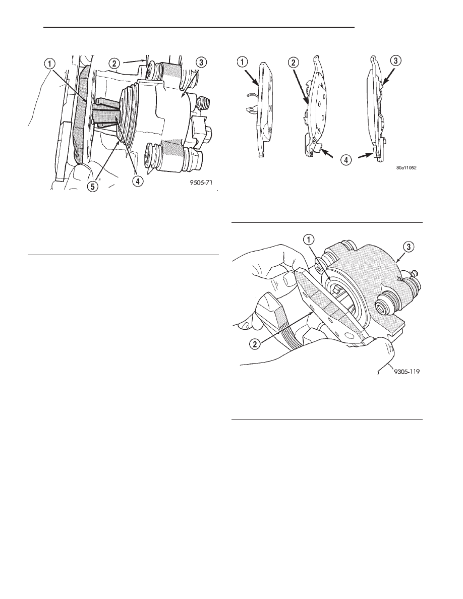
Fig. 86 Removing Inboard Brake Shoe

1 – INBOARD BRAKE SHOE
2 – HANGER WIRE
3 – CALIPER ASSEMBLY
4 – RETAINING CLIP
5 – PISTON

Fig. 87 Front Brake Shoe Assembly Identification

1 – INBOARD BRAKE SHOE
2 – LEFT OUTBOARD BRAKE SHOE
3 – RIGHT OUTBOARD BRAKE SHOE
4 – WEAR INDICATOR

Fig. 88 Installing Inboard Brake Shoe Assembly

1 – PISTON
2 – BRAKE SHOE
3 – CALIPER ASSEMBLY

JX

BRAKES

5 - 39

REMOVAL AND INSTALLATION (Continued)

NOTE: When installing guide pin bolts, extreme
caution should be taken not to cross thread the cal-
iper guide pin bolts.

(8) Install the caliper guide pin bolts (Fig. 81) and

tighten to a torque of 22 N·m (16 ft. lbs.).

(9) Install the wheel and tire assembly.
(10) Tighten the wheel mounting stud nuts in

proper sequence until all nuts are torqued to half
specification. Then repeat the tightening sequence to
the full specified torque of 135 N·m (100 ft. lbs.).

(11) Remove jackstands or lower hoist.
(12) Check brake fluid level.

NOTE: Before vehicle is moved after any brake ser-
vice work, pump the brake pedal several times to
insure the vehicle has a firm brake pedal.

(13) Road test the vehicle and make several stops

to wear off any foreign material on the brakes and to
seat the brake shoes.

DISC BRAKE CALIPER (REAR)

NOTE: Before proceeding, review SERVICE WARN-
INGS AND CAUTIONS at the beginning of REMOVAL
AND INSTALLATION in this section.

REMOVAL

(1) Raise vehicle on jackstands or centered on a

hoist. See Hoisting in the Lubrication and Mainte-
nance section of this manual.

(2) Remove rear wheels and tires from vehicle.
(3) Remove the 2 guide pin bolts mounting the cal-

iper to the adapter (Fig. 90).

(4) Remove caliper from adapter and rotor by first

rotating top of caliper away from the adapter, and
then lifting the caliper off lower machined abutment
on adapter (Fig. 91).

Fig. 89 Installing Brake Caliper

1 – ROTOR
2 – INSTALL THIS END OF CALIPER UNDER STEERING

KNUCKLE FIRST

3 – OUTBOARD BRAKE SHOE
4 – STEERING KNUCKLE
5 – DISC BRAKE CALIPER

Fig. 90 Caliper Guide Pin Bolts

1 – DISC BRAKE CALIPER
2 – CALIPER GUIDE PIN BOLTS

Fig. 91 Removing Caliper From Adapter

1 – BRAKING DISC
2 – CALIPER ADAPTER
3 – CALIPER
4 – LOWER MACHINED ADAPTER ABUTMENT

5 - 40

BRAKES

JX

REMOVAL AND INSTALLATION (Continued)

(5) Support the caliper from the rear strut to pre-

vent weight of caliper from damaging the flexible
brake hose (Fig. 92).

INSTALLATION

NOTE: Step 1 below is only required when install-
ing the disc brake caliper, after new brake shoes
have been installed.

(1) Completely retract caliper piston back into pis-

ton bore of caliper assembly.

(2) Lubricate both adapter abutments with a lib-

eral amount of Mopar

t Multipurpose Lubricant, or

equivalent.

(3) If removed, install the rotor on the hub making

sure it is squarely seated on the face of the hub (Fig.
93).

CAUTION: Use care when installing caliper assem-
bly onto adapter so the guide pin bushings and
sleeves do not get damaged by the mounting
bosses on adapter.

(4) Carefully lower caliper and brake shoes over

rotor reversing the removal procedure (Fig. 91).
Make sure that the caliper guide pin bolts, bushings
and sleeves are clear of the adapter bosses.

CAUTION: Extreme caution should be taken not to
cross thread the caliper guide pin bolts when they
are installed.

(5) Install the caliper guide pin bolts (Fig. 90).

Tighten the caliper guide pin bolts to a torque of 22
N·m (192 in. lbs.).

(6) Install wheels and tires.
(7) Tighten the wheel mounting stud nuts in

proper sequence until all nuts are torqued to half
specification. Then repeat the tightening sequence to
the full specified torque of 135 N·m (100 ft. lbs.).

(8) Remove jackstands or lower hoist.
(9) Check brake fluid level.

NOTE: Before moving vehicle, pump the brake
pedal several times to insure the vehicle has a firm
brake pedal.

(10) Road test the vehicle and make several stops

to wear off any foreign material on the brakes and to
seat the brake pads.

DISC BRAKE SHOES (REAR)

NOTE: Before proceeding, review SERVICE WARN-
INGS AND CAUTIONS at the beginning of REMOVAL
AND INSTALLATION in this section.

Fig. 92 Storing Caliper

1 – FLEX HOSE
2 – STRUT
3 – WIRE HANGER
4 – CALIPER ASSEMBLY

Fig. 93 Installing Rear Rotor

1 – BRAKING DISC
2 – DISC SHIELD
3 – HUB
4 – DRUM-IN-HAT PARKING BRAKE

JX

BRAKES

5 - 41

REMOVAL AND INSTALLATION (Continued)

REMOVAL

(1) Raise vehicle on jackstands or centered on a

hoist. See Hoisting in the Lubrication and Mainte-
nance section of this manual.

(2) Remove rear wheels and tires from vehicle.
(3) Remove the 2 guide pin bolts mounting the cal-

iper to the adapter (Fig. 94).

(4) Remove caliper from adapter and rotor by first

rotating the top of the caliper away from adapter,
and then lifting the caliper off the lower machined
abutment on adapter (Fig. 95).

(5) Support caliper from rear strut to prevent

weight of caliper from damaging the flexible brake
hose (Fig. 96).

(6) Remove rear rotor from hub/bearing (Fig. 97).

Then inspect drum-in-hat parking brake shoes and
parking brake braking surface on rotor for any signs
of excessive wear or damage. Replace parking brake
shoes if required.

(7) Remove outboard brake pad from caliper by

prying brake pad retaining clip over raised area on
caliper. Then slide brake pad down and off the cali-
per (Fig. 98).

(8) Pull inboard brake pad away from caliper pis-

ton, until retaining clip is free from cavity in piston.
(Fig. 99).

CALIPER INSPECTION

Check caliper for piston seal leaks (brake fluid in

and around boot area and inboard lining) and for any
ruptures of the piston dust boot. If boot is damaged,
or fluid leak is visible, disassemble caliper and
install a new seal and boot, (and piston if scored).
Refer to Caliper Disassembly And Re-Assembly Pro-
cedures in Disc Brake Caliper Service in this section
of the service manual.

Fig. 94 Caliper Guide Pin Bolts

1 – DISC BRAKE CALIPER
2 – CALIPER GUIDE PIN BOLTS

Fig. 95 Caliper Removal/Installation

1 – BRAKING DISC
2 – CALIPER ADAPTER
3 – CALIPER
4 – LOWER MACHINED ADAPTER ABUTMENT

Fig. 96 Storing Caliper

1 – FLEX HOSE
2 – STRUT
3 – WIRE HANGER
4 – CALIPER ASSEMBLY

5 - 42

BRAKES

JX

REMOVAL AND INSTALLATION (Continued)


Content   ..  192  193  194  195   ..