Chrysler Stratus Convertible. Manual - part 182


  Index      Chrysler     Chrysler Stratus Convertible - service repair manual 1995-2000 year


Search            


Content   ..  180  181  182  183   ..


Chrysler Stratus Convertible. Manual - part 182


(16) Lower vehicle.
(17) Check for correct fluid level in transaxle

assembly. Refer to Group 21, Transaxle for the cor-
rect fluid level checking procedure for the type of
transaxle being checked.

(18) Set front toe on vehicle to required specifica-

tion.

DISASSEMBLY AND ASSEMBLY

INNER TRIPOD JOINT SEAL BOOT

REMOVAL

To remove sealing boots from driveshafts, the

driveshaft assemblies must be removed from the
vehicle. See Servicing Driveshaft for the required
driveshaft removal and replacement procedure.

The inner tripod joints use no internal retention in

the tripod housing to keep the spider assembly in the
housing. Therefore, do not pull on the interconnect-
ing shaft to disengage tripod housing from transmis-
sion stub shaft. Removal in this manner will cause
damage to the inboard joint sealing boots.

(1) Remove the driveshaft requiring boot replace-

ment from the vehicle. See Servicing Driveshaft for
the required driveshaft removal procedure.

(2) Remove large boot clamp which retains inner

tripod joint sealing boot to tripod joint housing and
discard. Remove small clamp which retains inner tri-
pod joint sealing boot to interconnecting shaft and
discard. Remove the sealing boot from the tripod
housing and slide it down the interconnecting shaft.

CAUTION: When removing the tripod joint housing
from the spider assembly, hold the bearings in
place on the spider trunions to prevent the bearings
from falling away.

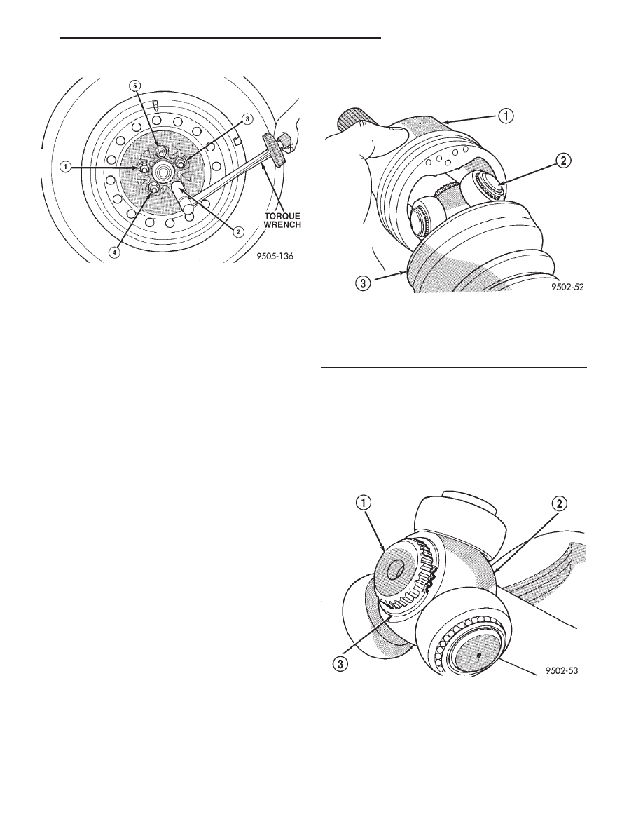
(3) Slide the tripod joint housing off the spider

assembly and the interconnecting shaft (Fig. 26).

(4) Remove snap ring which retains spider assem-

bly to interconnecting shaft (Fig. 27). Remove the
spider assembly from interconnecting shaft. If spider
assembly will not come off interconnecting shaft by
hand, it can be removed by tapping spider assembly
with a brass drift (Fig. 28). Do not hit the outer
tripod bearings in an attempt to remove spider
assembly from interconnecting shaft.

(5) Slide sealing boot off interconnecting shaft.

Fig. 25 Wheel Lug Torquing Sequence

Fig. 26 Spider Assembly Removal from Tripod Joint

Housing

1 – TRIPOD JOINT HOUSING
2 – SPIDER ASSEMBLY
3 – SEALING BOOT

Fig. 27 Spider Assembly Retaining Snap Ring

1 – INTERCONNECTING SHAFT
2 – SPIDER ASSEMBLY
3 – RETAINING SNAP RING

JX

DIFFERENTIAL AND DRIVELINE

3 - 9

REMOVAL AND INSTALLATION (Continued)

(6) Thoroughly clean and inspect spider assembly,

tripod joint housing, and interconnecting shaft for
any signs of excessive wear. If any parts show
signs of excessive wear, the driveshaft assembly
will require replacement. Component parts of
these driveshaft assemblies are not serviceable.

INSTALLATION

NOTE: The inner tripod joint sealing boots are
made from two different types of material. High
temperature applications use silicone rubber where
as standard temperature applications use hytrel
plastic. The silicone sealing boots are soft and pli-
able. The Hytrel sealing boots are stiff and rigid.
The replacement sealing boot MUST BE the same
type of material as the sealing boot which was
removed.

(1) Slide inner tripod joint seal boot retaining

clamp, onto interconnecting shaft. Then, slide the
replacement inner tripod joint sealing boot onto the
interconnecting shaft. Inner tripod joint seal boot
MUST be positioned on interconnecting shaft,
so the raised bead on the inside of the seal boot
is in groove on interconnecting shaft (Fig. 29).

(2) Install spider assembly onto interconnecting

shaft (Fig. 30). Spider assembly must be installed on
interconnecting shaft far enough to fully install spi-
der retaining snap ring. If spider assembly will not
fully install on interconnecting shaft by hand, it can
be installed by tapping the spider body with a brass
drift (Fig. 31). Do not hit the outer tripod bear-

ings in an attempt to install spider assembly on
interconnecting shaft.

(3) Install the spider assembly to interconnecting

shaft retaining snap ring into groove on end of inter-
connecting shaft (Fig. 32). Be sure the snap ring is
fully seated into groove on interconnecting shaft.

(4) Distribute 1/2 the amount of grease provided in

the seal boot service package (DO NOT USE ANY
OTHER TYPE OF GREASE) into tripod housing. Put
the remaining amount into the sealing boot.

(5) Align tripod housing with spider assembly and

then slide tripod housing over spider assembly and
interconnecting shaft (Fig. 33).

Fig. 28 Spider Assembly Removal from

Interconnecting Shaft

1 – SPIDER ASSEMBLY
2 – DO NOT HIT SPIDER ASSEMBLY BEARINGS WHEN

REMOVING SPIDER ASSEMBLY

3 – BRASS DRIFT
4 – INTERCONNECTING SHAFT

Fig. 29 Sealing Boot Installation on Interconnecting

Shaft

1 – SEALING BOOT
2 – RAISED BEAD IN THIS AREA OF SEALING BOOT
3 – GROOVE
4 – INTERCONNECTING SHAFT

Fig. 30 Spider Assembly Installation on

Interconnecting Shaft

1 – SPIDER ASSEMBLY
2 – INTERCONNECTING SHAFT

3 - 10

DIFFERENTIAL AND DRIVELINE

JX

DISASSEMBLY AND ASSEMBLY (Continued)

(6) Install inner tripod joint seal boot to intercon-

necting shaft clamp evenly on sealing boot.

(7) Clamp sealing boot onto interconnecting shaft

using crimper, Special Tool C-4975-A and the follow-
ing procedure. Place crimping tool C-4975-A over
bridge of clamp (Fig. 34). Tighten nut on crimping
tool C-4975-A until jaws on tool are closed completely
together, face to face (Fig. 35).

CAUTION: Seal must not be dimpled, stretched or
out of shape in any way. If seal is NOT shaped cor-
rectly, equalize pressure in seal and shape it by
hand.

(8) Position sealing boot into the tripod housing

retaining groove. Install seal boot retaining clamp
evenly on sealing boot.

Fig. 31 Installing Spider Assembly on

Interconnecting Shaft

1 – DO NOT HIT BEARINGS WHEN INSTALLING THE SPIDER

ASSEMBLY

2 – SPIDER ASSEMBLY
3 – INTERCONNECTING SHAFT
4 – BRASS DRIFT

Fig. 32 Spider Assembly Retaining Snap Ring

Installed

1 – INTERCONNECTING SHAFT
2 – SPIDER ASSEMBLY
3 – RETAINING SNAP RING

Fig. 33 Installing Tripod Housing on Spider

Assembly

1 – TRIPOD JOINT HOUSING
2 – SPIDER ASSEMBLY
3 – SEALING BOOT

Fig. 34 Crimping Tool Installed on Sealing Boot

Clamp

1 – SPECIAL TOOL C-4975A
2 – INTERCONNECTING SHAFT
3 – CLAMP
4 – SEALING BOOT

JX

DIFFERENTIAL AND DRIVELINE

3 - 11

DISASSEMBLY AND ASSEMBLY (Continued)

CAUTION: The

following

positioning

procedure

determines the correct air pressure inside the inner
tripod joint assembly prior to clamping the sealing
boot to inner tripod joint housing. If this procedure
is not done prior to clamping sealing boot to tripod
joint

housing

sealing

boot

durability

can

be

adversely affected.

CAUTION: When venting the inner tripod joint
assembly, use care so inner tripod sealing boot
does not get punctured, or in any other way dam-
aged. If sealing boot is punctured, or damaged in
any way while being vented, the sealing boot can
not be used.

(9) Insert a trim stick between the tripod joint and

the sealing boot to vent inner tripod joint assembly
(Fig. 36). When inserting trim stick between tri-
pod housing and sealing boot ensure trim stick
is held flat and firmly against the tripod hous-
ing. If this is not done damage to the sealing
boot can occur. 
If inner tripod joint has a Hytrel
(hard plastic) sealing boot, be sure trim stick is
inserted between soft rubber insert and tripod hous-
ing not the hard plastic sealing boot and soft rubber
insert.

(10) With trim stick inserted between sealing boot

and tripod joint housing, position the interconnecting
shaft so it is at the center of its travel in the tripod
joint housing. Remove the trim stick from between
the sealing boot and the tripod joint housing. This
procedure will equalize the air pressure in the

tripod joint, preventing premature sealing boot
failure.

(11) Position trilobal boot to interface with the tri-

pod housing. The lobes of the boot must be properly
aligned with the recess’s of the tripod housing.

(12) Clamp tripod joint sealing boot to tripod joint,

using required procedure for type of boot clamp
application.

CRIMP TYPE BOOT CLAMP

If seal boot uses crimp type boot clamp:
• Clamp sealing boot onto tripod housing using

Crimper, Special Tool C-4975-A.

• Place crimping tool C-4975-A over bridge of

clamp (Fig. 37).

• Tighten nut on crimping tool C-4975-A until

jaws on tool are closed completely together, face to
face (Fig. 38).

LATCHING TYPE BOOT CLAMP

If seal boot uses low profile latching type boot

clamp:

• Clamp sealing boot onto tripod housing using

clamp locking tool, Snap-On YA3050 or an equiva-
lent.

• Place prongs of clamp locking tool in the holes of

the clamp (Fig. 39).

• Squeeze tool together until top band of clamp is

latched behind the two tabs on lower band of clamp
(Fig. 40).

(13) Install the driveshaft back on the vehicle. See

Servicing Driveshaft, for the required driveshaft
installation procedure.

Fig. 35 Sealing Boot Retaining Clamp Installed

1 – CLAMP
2 – JAWS OF SPECIAL TOOL C-4975A MUST BE CLOSED

COMPLETELY TOGETHER HERE

3 – INTERCONNECTING SHAFT
4 – SEALING BOOT

Fig. 36 Trim Stick Inserted for Venting Tripod Joint

1 – INNER TRIPOD JOINT SEALING BOOT
2 – SEALING BOOT CLAMP
3 – INNER TRIPOD JOINT HOUSING
4 – TRIM STICK

3 - 12

DIFFERENTIAL AND DRIVELINE

JX

DISASSEMBLY AND ASSEMBLY (Continued)


Content   ..  180  181  182  183   ..