Chrysler Stratus Convertible. Manual - part 103


  Index      Chrysler     Chrysler Stratus Convertible - service repair manual 1995-2000 year


Search            


Content   ..  101  102  103  104   ..


Chrysler Stratus Convertible. Manual - part 103


GEARSHIFT PATTERN

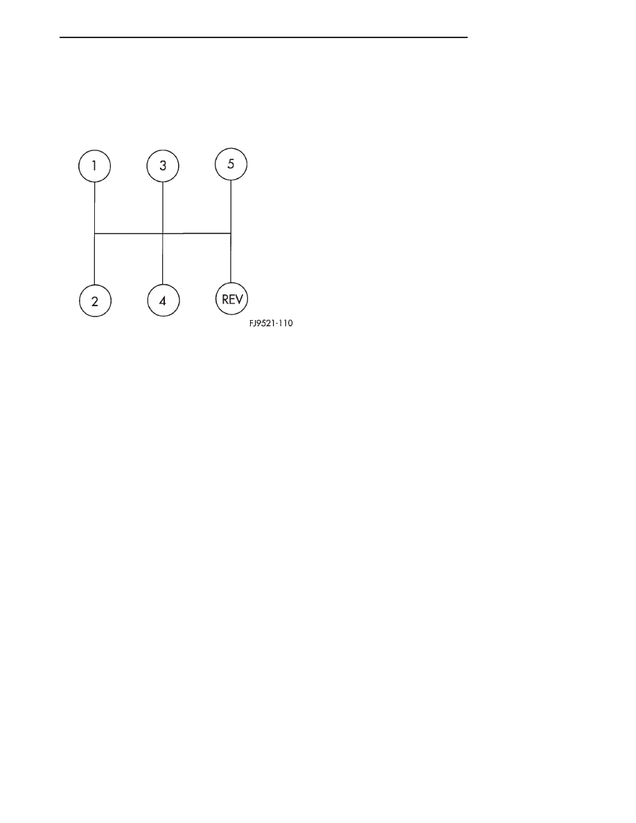
The NV T350 (A-578) transaxle shift pattern is a

modified H–pattern (Fig. 4). Overdrive fifth and
reverse gears are in–line and outboard of the first
through fourth gear positions.

LUBRICANT/ADDITIVES

NV T350 (A-578) transaxles use Mopar

t Type M.

S. 9417 Manual Transaxle Fluid. Hypoid gear lube,
engine oil, and/or automatic transmission fluid
should not be used in this transaxle. 
Hard shift-
ing effort, bearing, gear, and/or synchronizer failure
may occur if incorrect fluid is used.

The addition of any fluids to the transaxle, other

than the fluid listed above, is not recommended. An
exception to this policy is the use of special dyes to
aid in detecting fluid leaks. The use of transmission
sealers should be avoided, since they may adversely
affect seals.

SEALANTS

The sealant used to seal the transaxle case halves

and input bearing is Mopar

t Gasket Maker, Loctitet

518, or equivalent. The sealant used for the bearing
end plate cover is Mopar

t RTV.

GEARSHIFT LEVERS

DESCRIPTION

The shift levers are serviceable in the vehicle. The

shift levers are different from each other and do not
interchange.

AXLE SEALS

DESCRIPTION

The axle shaft seals are identical for both sides of

the differential and will interchange.

DIAGNOSIS AND TESTING

COMMON PROBLEM CAUSES

The majority of transaxle malfunctions are a result

of:

• Insufficient lubrication

• Incorrect lubricant

• Misassembled or damaged internal components

• Improper operation

HARD SHIFTING

Hard shifting may be caused by a misadjusted

crossover cable. If hard shifting is accompanied by
gear clash, synchronizer clutch and stop rings or gear
teeth may be worn or damaged.

Misassembled synchronizer components also cause

shifting problems. Incorrectly installed synchronizer
sleeves, struts, or springs can cause shift problems.

NOISY OPERATION

Transaxle noise is most often a result of worn or

damaged components. Chipped, broken gear or syn-
chronizer teeth, and brinnelled, spalled bearings all
cause noise.

Abnormal wear and damage to the internal compo-

nents is frequently the end result of insufficient
lubricant.

SLIPS OUT OF GEAR

Transaxle disengagement may be caused by mis-

aligned or damaged shift components, or worn teeth
on the drive gears or synchronizer components. Incor-
rect assembly also causes gear disengagement.

LOW LUBRICANT LEVEL

Insufficient transaxle lubricant is usually the

result of leaks, or inaccurate fluid level check or refill
method. Leakage is evident by the presence of oil
around the leak point. If leakage is not evident, the
condition is probably the result of an underfill.

If air–powered lubrication equipment is used to fill

a transaxle, be sure the equipment is properly cali-
brated. Equipment out of calibration can lead to an
underfill condition.

Fig. 4 NV T350 (A-578) Shift Pattern

JX

TRANSAXLE

21 - 3

DESCRIPTION AND OPERATION (Continued)

CLUTCH PROBLEMS

Worn, damaged, or misaligned clutch components

can cause difficult shifting, gear clash, and noise.

A worn or damaged clutch disc, pressure plate, or

release bearing can cause hard shifting and gear
clash.

SERVICE PROCEDURES

FLUID DRAIN AND FILL

All NV T350 (A-578) transaxles are equipped with a

fill plug. The fill plug is located on the left side of the
transaxle differential area (Fig. 5). The fluid level
should be within 3/16 inch from the bottom of the tran-
saxle fill hole (vehicle must be level when checking).

All NV T350 (A-578) transaxles are equipped with

a drain plug. The drain plug is located on the lower
right side of the transaxle differential housing (Fig.
6). Tighten drain plug to 28 N·m (250 in. lbs.)

Fill transaxle to capacity. Refer to following chart.

Wipe the outside of the transaxle if any lubricant
spills.

REMOVAL AND INSTALLATION

GEARSHIFT KNOB

REMOVAL

(1) Pull shifter boot down and away from shifter

roll pin.

(2) Pry legs of shift knob away from shift lever roll

pin using a flat blade pry tool (Fig. 7).

(3) Remove knob from shifter handle (Fig. 8).

Fig. 5 Fill Plug Location

1 – RUBBER FILL PLUG
2 – LEFT DRIVESHAFT SEAL

Fig. 6 Drain Plug Location

1 – RIGHT DRIVESHAFT SEAL
2 – DRAIN PLUG

NV T350 (A-578) MANUAL TRANSAXLE FLUID

FILL

TRANSAXLE

METRIC

MEASURE

U. S.

MEASURE

NV T350

1.9-2.2 Liters

2.0-2.3 Quarts

NV T350HD

2.4-2.7 Liters

2.5-2.8 Quarts

NOTE: Two 5 speed transaxles are available. Refer
to capacity label on case near left driveshaft for
identification.

Fig. 7 Gearshift Knob

1 – KNOB
2 – CLIPS
3 – BOOT

21 - 4

TRANSAXLE

JX

DIAGNOSIS AND TESTING (Continued)

INSTALLATION

(1) Install shifter knob to shifter mechanism until

legs snap over roll pin.

(2) Pull shifter boot up to seat around shifter

knob.

GEARSHIFT BOOT

REMOVAL

(1) Remove shifter knob. Refer to gearshift knob

removal and installation.

(2) Remove shifter boot/bezel assembly from con-

sole. (Fig. 9).

INSTALLATION

(1) Install boot/bezel assembly to console. Apply

hand pressure until retaining clips are seated to the
console assembly.

(2) Install shifter knob. Refer to gearshift knob

removal and installation.

GEARSHIFT CABLES

REMOVAL

(1) Disconnect battery negative cable at shock

tower.

(2) Remove air cleaner assembly.

(3) Disconnect gear shift cable ends from transaxle

shift levers (Fig. 10).

CAUTION: Pry up with equal force on both sides of
shifter cable isolator bushings to avoid damaging
cable isolator bushings.

Fig. 8 Shifter Knob Removal/Installation

1 – SHIFTER KNOB

Fig. 9 Boot Removal

1 – SHIFTER BOOT/BEZEL
2 – CONSOLE

Fig. 10 Shift Cable Removal

1 – SCREWDRIVERS
2 – SHIFT CABLE

JX

TRANSAXLE

21 - 5

REMOVAL AND INSTALLATION (Continued)

(4) Remove cable to bracket retaining clips at tran-

saxle.

CAUTION: It is recommended that new cable retain-
ing clips be used for reinstallation.

(5) Pull cables up out of transaxle bracket.
(6) Remove gearshift knob and boot. Refer to Knob

and Boot Removal in this section.

(7) Remove forward and rear console assemblies.

Refer to Group 23, Body for the proper procedures.

(8) Remove floor pan grommet from floor pan.
(9) Remove cable retaining clips at shifter (Fig.

11).

CAUTION: It is recommended that new cable retain-
ing clips be used for reinstallation.

(10) Disconnect shift cables from shifter. Pry with

equal force on both sides of shifter cable isolator
bushings to avoid damaging bushings.

(11) Lift vehicle on hoist. Pry shift cable grommet

from floor pan.

(12) Detach cables from cable support clips.
(13) Remove shift cables from vehicle.

INSTALLATION

(1) To install, reverse removal procedure. After

cables have been replaced, cable adjustment should
be checked. Refer to cable adjustment procedure in
this section.

CAUTION: Gearshift cable bushings must not be
lubricated or the bushings will swell and split.

CAUTION: Only the crossover cable is adjustable.
The selector cable does not have any adjustment
capabilities.

GEARSHIFT MECHANISM REPLACEMENT

REMOVAL

(1) Remove shifter knob and boot. refer to Shifter

Knob And Boot Removal procedure in this section.

(2) Remove forward and rear console assemblies.

Refer to Group 23, Body for the proper procedures.

(3) Disconnect gearshift cables at shifter end.

Refer to Gearshift Cable Removal in this section

(4) Remove retaining nuts at the base of the gear-

shift mechanism (Fig. 12). Remove shifter.

INSTALLATION

(1) For installation, reverse removal procedure.
(2) Torque gearshift mechanism nuts to 17 N·m

(150 in. lbs.).

VEHICLE SPEED SENSOR DRIVE GEAR

REMOVAL

(1) Raise vehicle on hoist.
(2) Remove wiring connector from speed sensor

(Fig. 13).

CAUTION: Clean area around speed sensor before
removing. This will prevent the possibility of dirt
from entering the transaxle during speed sensor
removal.

Fig. 11 Cable Retaining Clips

1 – CABLE CLIPS
2 – SHIFTER

Fig. 12 Gearshift Mechanism

1 – GEARSHIFT MECHANISM
2 – NUT (5)
3 – GEARSHIFT CABLES

21 - 6

TRANSAXLE

JX

REMOVAL AND INSTALLATION (Continued)


Content   ..  101  102  103  104   ..