Chrysler New Yorker. Manual - part 108
POWER MIRRORS
CONTENTS
page
page
DESCRIPTION AND OPERATION
HEATED MIRROR . . . . . . . . . . . . . . . . . . . . . . . . 1
INTRODUCTION . . . . . . . . . . . . . . . . . . . . . . . . . 1
DIAGNOSIS AND TESTING
AUTOMATIC DAY/NIGHT INSIDE MIRROR . . . . 1
HEATED MIRROR . . . . . . . . . . . . . . . . . . . . . . . . 2
MIRROR MOTOR . . . . . . . . . . . . . . . . . . . . . . . . 2
MIRROR SWITCH . . . . . . . . . . . . . . . . . . . . . . . . 2
REMOVAL AND INSTALLATION
MIRROR SWITCH . . . . . . . . . . . . . . . . . . . . . . . . 3
MIRROR SWITCH . . . . . . . . . . . . . . . . . . . . . . . . 3
DESCRIPTION AND OPERATION
INTRODUCTION
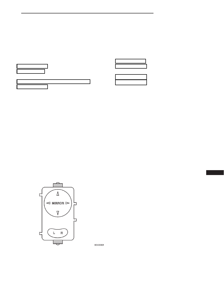
Power mirrors are controlled by a single switch
assembly located on the driver’s door trim panel. The
switch has a rocker button marked L (left) and R
(right) for mirror selection and a single platform but-
ton for mirror UP, DOWN, RIGHT and LEFT move-
ment (Fig. 1).
The motors which operate the mirrors are part of
the mirror assembly and cannot be replaced sepa-
rately.
The vehicle is equipped with an Ignition-Off Draw
Fuse which is used when it is originally shipped from
the factory. This fuse is located in the Junction Block
and helps to prevent battery discharge during stor-
age when disconnected.
This fuse is included in the power mirror circuity
and should be checked if the mirrors are inoperative.
HEATED MIRROR
Heated mirrors are available with Memory Mirrors
and Rear Window Defogger only. The heated mirror
is controlled by the rear window defogger switch.
Only time that the heated mirror is on is when the
rear window defogger is on. The mirror should
become warm to the touch.
DIAGNOSIS AND TESTING
AUTOMATIC DAY/NIGHT INSIDE MIRROR
Operational test:
• Turn ignition switch to the ON position with the
vehicle in park.
• Place mirror switch in the high position.
• Cover the forward facing sensor with dark cloth
to keep out any ambient light.
• Shine a light into the rear facing sensor, watch
to see if the mirror darkens.
With the mirror darkened, place the vehicle in
reverse, the mirror should return to its normal con-
dition.
If the above conditions are met the mirror is oper-
ating properly. If not OK, test voltage.
Test three way connector harness.
(1) Pin 1 Ignition Switch in run position, should
have battery voltage.
(2) Pin 2 Should have continuity to Ground.
(3) Pin 3 Senses when the transmission is in
reverse. There should be battery voltage present
when transmission is in the reverse position.
(4) If test is OK replace Mirror.
(5) If not refer, to Group 8W, Wiring Diagrams
manual to test the circuits.
Fig. 1 Power Mirror Switch
LH
POWER MIRRORS
8T - 1