Chrysler New Yorker. Manual - part 99
ton operation. Note this does not check the EBL sys-
tem. There are no fault codes that can check for the
EBL grid, relay, or wiring. Refer to steps 2 and 3 for
system test.
(2) Perform system test with voltmeter.
Check voltages at rear grid relay and refer to Rear
Widow Defogger Relay Test table.
A/C-HEATER AND ATC CONTROL HEAD
Refer to Group 24, Heating and Air Conditioning
for instructions on how to use the DRB lll scan tool
or the control head self-diagnostics to test the part.
The problem is not with the control head if no trou-
ble codes are found. The next step should be to check
the rest of the system after the A/C-Heater or ATC
control is checked.
SYSTEM TEST
(1) Start engine. With the engine running, push
the Rear Window Defogger button on the ATC or
Manual A/C Heater Control Head. The button LED
indicator should light. If the EBL indicator does not
light on the MANUAL-A/C HEATER CONTROL,
then there may be a wiring problem. This may also
indicate that the BCM will not complete the circuit
to ground that is required to energize the EBL relay
coil (non-ATC vehicles only). Refer to EBL Relay
Test. On ATC vehicles, the LED indicator may light
when the BCM failed to complete the circuit to
ground required to energize the EBL relay coil.
(2) Using a DC voltmeter with a 0-15 volt range,
connect the negative lead to a known good vehicle
electrical ground.
(3) Touch the positive bus bar and check voltage.
The voltage should be above 11 volts. Push the Rear
Window Defogger button to turn off the indicator.
The measured voltage should be 0 volts. If these volt-
ages are correct then the problem is with the Rear
Window Grid or Grid ground electrical connection. Go
to the Grid Lines test to check the Grid and ground
connection.. If there is no voltage to the rear window
defogger grid when the system is ON, then go to the
Fuse and Electrical Short Test.
GRID TEST
The horizontal grid line and vertical bus bar line is
printed and fired on the inside surface of the rear
window glass. These comprise and electrical circuit.
The electrically conductive lines are composed of a
silver ceramic material which when fired on glass
becomes bonded to the glass and is highly resistant
to abrasion. It is possible, however, that a break may
occur in and individual grid line resulting in no cur-
rent flow through the line. To detect breaks in grid
lines, the following procedure is required:
(1) Stop the engine. Connect the negative lead of a
0-25 volt range voltmeter to a known good vehicle
electrical ground.
(2) Start the engine and push the rear window
defogger button to turn on the system.
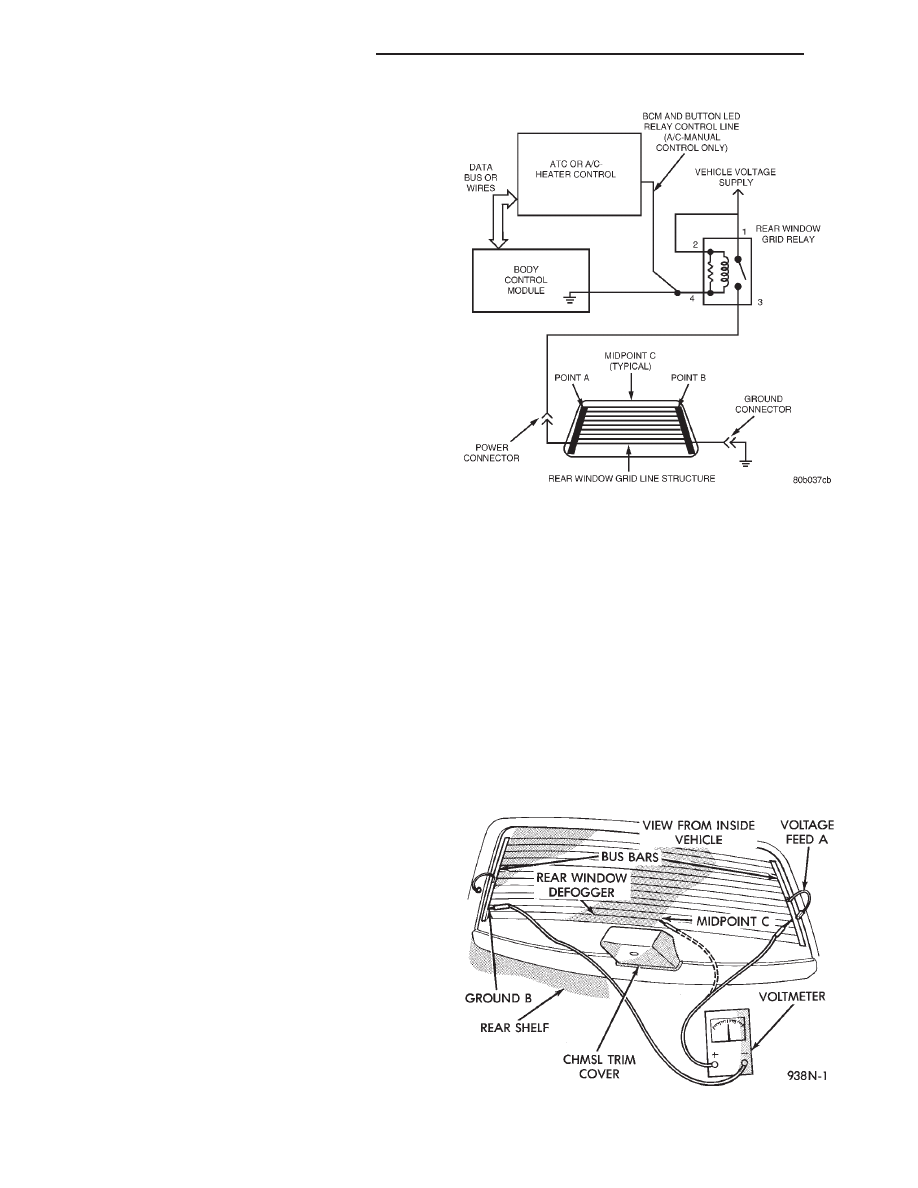
(3) Touch the ground side (point B) of the Rear
Window Defogger Grid. The voltage measured should
be below 1 volt. If the voltage is greater than 1 volt
then check the voltage on each grid line at the Mid-
Point with the positive lead. If the voltage is not
approximately 6 volts or half the voltage measured
on the positive rear window grid bus bar, then the
grid line is bad. The break in the grid can be found
by moving the probe along the line until the voltage
changes. The area where the voltage changes is
where the open circuit is.
Fig. 2 System Electrical Circuit
Fig. 3 Grid Line Test
8N - 2
ELECTRICALLY HEATED SYSTEMS
LH
DIAGNOSIS AND TESTING (Continued)