Chrysler New Yorker. Manual - part 35
INLET AND OUTLET VALVES AND SOLENOIDS
There are four inlet valves and four outlet valves,
one of each per wheel. Each valve is controlled by a
solenoid. Inlet valves are normally open when the
solenoid is off. Outlet valves are normally closed
when the solenoid is off. When ABS braking occurs,
the CAB energizes and de-energizes the solenoids,
opening and closing the valves as necessary.
• Inlet Valve Open/Outlet Valve Closed — This
is the position the valves are in during a pressure-
build cycle, and also during normal, non-ABS brak-
ing. Fluid is allowed to enter the brake circuit
through the open inlet valve. Fluid is blocked from
the decay circuit by the closed outlet valve. Fluid
enters the valve block and flows to the wheel brake.
• Inlet Valve Closed/Outlet Valve Open — This
is the position the valves are in during a pressure-
decay cycle. Fluid is blocked from entering the brake
circuit by the closed inlet valve. The fluid flows back
from the wheel brake through the open outlet valve
into the decay circuit. The decay circuit connects to a
fluid accumulator where the fluid is stored until it is
needed.
• Inlet Valve Closed/Outlet Valve Closed —
This is the position the valves are in during a pres-
sure-hold cycle. Fluid is blocked from entering the
brake circuit by the closed inlet valve. Fluid is pre-
vented from entering the decay circuit by the closed
outlet valve. Brake pressure is held trapped at the
wheel brake in order to hold the brake steady.
ABS FLUID ACCUMULATORS
There are two fluid accumulators in all hydraulic
control units, one each for the primary and secondary
hydraulic circuits. The fluid accumulators tempo-
rarily store brake fluid that is removed from the
wheel brakes during an ABS cycle. This fluid is then
used by the pump in the valve body to provide build
pressure for the brake hydraulic system.
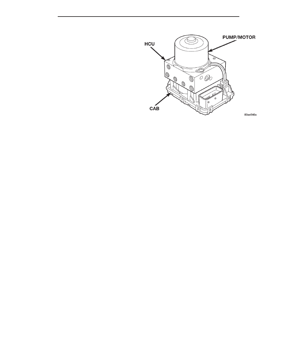
HCU PUMP/MOTOR
The HCU (Fig. 2) contains 2 pump assemblies, one
for the primary and one for the secondary hydraulic
circuit of the brake system. Both pumps are driven
by a common electric motor (Fig. 2) which is part of
the HCU. The pumps draw brake fluid from the fluid
accumulators to supply build pressure to the brakes
during an ABS stop. The pump motor runs during
the drive-off cycle as a check and during an ABS stop
and is controlled by the CAB. The Pump/Motor
Assembly is not a serviceable item. If the pump/mo-
tor requires replacement the complete HCU (Fig. 2)
(minus the CAB) must be replaced.
ABS FUSES
The fuse for the ABS pump motor and the ABS
system are located in the Power Distribution Center
(PDC). The PDC is located on the drivers side of the
engine compartment forward of the strut tower. Refer
to the diagram inside the PDC cover, for the exact
location of fuses.
ABS RELAYS
On the Mark 20 Antilock Brake System, both the
pump motor relay and the system relay are inte-
grated into the CAB. If either relay is diagnosed as
not functioning properly, the CAB will need to be
replaced. Refer to Controller Antilock Brakes in the
Removal And Installation Section in this group of the
service manual for the procedure.
WHEEL SPEED SENSORS
One Wheel Speed Sensor (WSS) is located at each
wheel, and sends a small AC signal to the control
module CAB. This signal is generated by magnetic
induction created when a toothed sensor ring (tone
wheel) passes the stationary magnetic wheel speed
sensor. The CAB converts the AC signal generated at
each wheel into a digital signal. If a wheel locking
tendency is detected by the CAB, it will then modu-
late hydraulic pressure via the HCU to prevent the
wheel(s) from locking.
Each front wheel speed sensor is attached to a boss
in the steering knuckle. The tone wheel is part of the
outboard constant velocity joint . Each rear wheel
speed sensor, on rear disc brake applications, is
mounted to the rear brake caliper adapter and the
rear tone wheel is an integral part of the rear wheel
hub/bearing assembly.
Fig. 2 Teves Mark 20 HCU Pump/Motor
5 - 54
BRAKES
300M
DESCRIPTION AND OPERATION (Continued)