Chrysler New Yorker. Manual - part 27
Only double wall 4.75mm (3/16 in.) steel tubing
should be used for replacement of the chassis brake
tubes. The chassis brake tubes used on this
vehicle are coated with a zinc alloy and alumi-
num rich coating referred to as Prokote 2000. If
a chassis brake tube requires replacement, only
brake tubing with the same coating should be
used as a service replacement. Care should be
taken when replacing brake tubing, to be sure the
proper bending and flaring tools and procedures are
used, to avoid kinking. Do not route the tubes
against sharp edges, moving components or into hot
areas. All tubes should be properly attached with rec-
ommended retaining clips and fasteners.
Care must be taken when servicing components to
avoid damage to the flexible stainless steel hoses
between the master cylinder and junction block or
antilock hydraulic control unit.
ISO STYLE TUBE FLARING PROCEDURE
CAUTION:
ALWAYS USE THE PROPER TYPE OF
ISO FLARING TOOL AND REQUIRED PROCEDURE,
WHEN TUBE FLARING IS REQUIRED WHEN SER-
VICING THE VEHICLES HYDRAULIC BRAKE SYS-
TEM.
THIS
IS
REQUIRED
TO
ENSURE
THE
INTEGRITY OF THE VEHICLE’S HYDRAULIC BRAK-
ING SYSTEM.
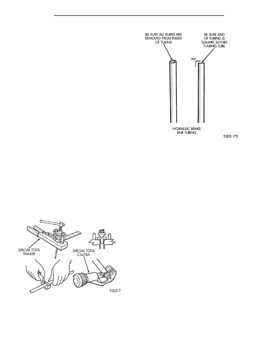
Using Tubing Cutter, Special Tool C-3478-A or
equivalent, cut off damaged seat on tubing (Fig. 27).
Ream out any burrs or rough edges showing on
inside of tubing. This will make the ends of tubing
square (Fig. 28) and ensure better seating of flared
end tubing. Be sure to put the tube nut on tub-
ing before the tubing is flared.
CAUTION:
All ISO style tubing flares are of metric
dimensions. When performing any service proce-
dures on a vehicle using ISO style tubing flares,
metric size tubing of 4.75 mm MUST be used with
metric ISO tube flaring equipment.
To create a (metric) ISO style tubing flare, Use
Snap-On Flaring Tool TFM-428, (Fig. 27) or equiva-
lent. See (Fig. 29) and proceed with the steps listed
below. Be sure to place the tubing nut on tube
before proceeding to flare the tubing.
(1) Carefully prepare the end of the tubing to be
flared. Be sure the end of the tubing is square and
all burrs on the inside of the tubing are removed
(Fig. 28). This preparation is essential to obtain
the correct form of a (metric) ISO tubing flare.
(2) Open the jaws of the Flaring Tool. Align the
jaws of the flaring tool around the tubing. Close the
jaws of the Flaring Tool around the tubing, but do
not lock the tubing in place.
(3) Position tubing in jaws of the Flaring Tool so
that it is flush with top surface of flaring tool bar
assembly (Fig. 29).
(4) Install the correct size adaptor for the brake
tubing being flared, on the feed screw of the yoke
assembly. Center the yoke and adapter over the end
of the tubing. Apply lubricant to the adapter area
that contacts the brake tubing. Make sure the
adapter pilot is fully inserted in the end of the brake
tubing. Tighten screw on yoke assembly until the
adaptor has seated squarely on the surface of the bar
assembly (Fig. 29). This process will properly create
a metric ISO tubing flare.
Fig. 27 Cutting and Flaring of Brake Line Tubing
Fig. 28 Tube End Properly Prepared For Flaring
5 - 22
BRAKES
300M
SERVICE PROCEDURES (Continued)