Index Chrysler Chrysler Crossfire - service repair manual 2005 year
Search
Content .. 739 740 741 742 ..
Chrysler Crossfire. Manual - part 741
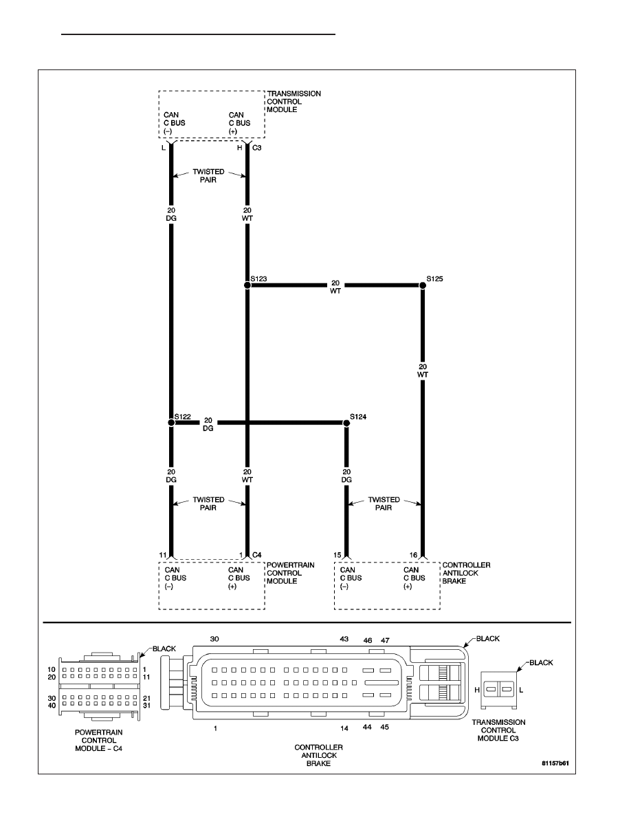
(P0720) CAN BUS CIRCUIT
ZH
NAG1 - ELECTRICAL DIAGNOSTICS
21 - 113