Chrysler Crossfire. Manual - part 365
CENTRAL LOCKING PUMP/SECURITY SYSTEM MODULE INTERNAL FAILURE (CONTINUED)
When Monitored and Set Condition
•
When Monitored: Continuous.
•
Set Condition: If the Central Locking Pump/Security System Module (CLP/SSM) detects an internal malfunc-
tion, the DTC is set.
POSSIBLE CAUSES
NO POWER TO CENTRAL LOCKING PUMP/SECURITY SYSTEM MODULE
CENTRAL LOCKING PUMP/SECURITY SYSTEM MODULE
For a complete Vehicle Theft Security System Circuit Diagram, (Refer to 8 - ELECTRICAL/VEHICLE THEFT SECU-
RITY - SCHEMATICS AND DIAGRAMS).
Diagnostic Test
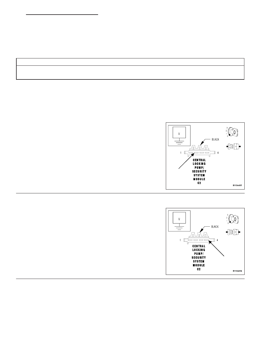
1.
MEASURE THE VOLTAGE OF THE CLP/SSM POWER CIRCUIT
Turn the ignition off.
Disconnect the CLP/SSM harness connector.
Measure the voltage of the Fused B(+) circuit (cavity 2) at the CLP/
SSM C2 harness connector.
Is the voltage between 12 and 16 volts?
Yes
>> Go to 2
No
>> System voltage must be between 12 and 16 volts. Repair
the voltage concern as necessary.
Perform VTSS VERIFICATION TEST.
2.
MEASURE THE VOLTAGE OF THE CLP/SSM POWER CIRCUIT
Measure the voltage of the Fused B(+) circuit (cavity 4) at the CLP/
SSM C2 harness connector.
Is the voltage between 12 and 16 volts?
Yes
>> Replace the Central Locking Pump/Security System Mod-
ule. (Refer to 8 - ELECTRICAL/VEHICLE THEFT SECU-
RITY/SENTRY
KEY
REMOTE
ENTRY
MODULE
-
REMOVAL).
Perform VTSS VERIFICATION TEST.
No
>> System voltage must be between 12 and 16 volts. Repair
the voltage concern as necessary.
Perform VTSS VERIFICATION TEST.
ZH
VEHICLE THEFT SECURITY - ELECTRICAL DIAGNOSTICS
8Q - 33