Chrysler Crossfire. Manual - part 93
NO CAN COMMUNICATIONS WITH PCM (CONTINUED)
When Monitored and Set Condition
•
When Monitored: With the ignition on.
•
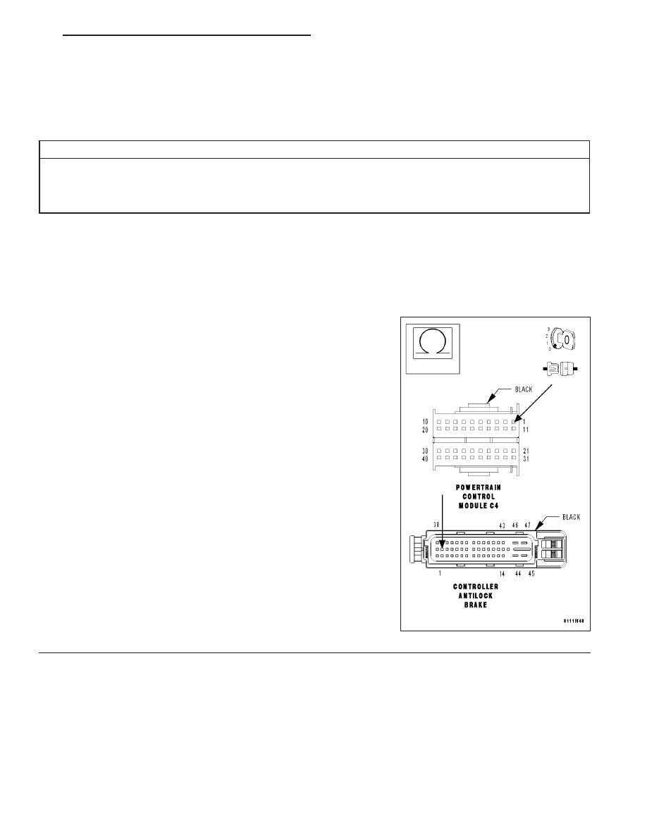
Set Condition: CAN Bus communication failure between the Controller Antilock Brake (CAB) and the Power-
train Control Module (PCM).
POSSIBLE CAUSES
CAN C BUS (+) CIRCUIT OPEN
CAN C BUS (-) CIRCUIT OPEN
CONTROLLER ANTILOCK BRAKE
For a complete Brake Assist System (BAS) Circuit Diagram (Refer to 5 - BRAKES/ELECTRICAL - SCHEMATICS
AND DIAGRAMS).
Diagnostic Test
1.
MEASURE THE RESISTANCE OF THE CAN C BUS (+) CIRCUIT
Turn the ignition off.
Disconnect the CAB harness connector.
Disconnect the PCM harness connector.
Note: Check connectors - Clean/repair as necessary.
Measure the resistance of the CAN C Bus (+) circuit from the CAB
harness connector to the PCM harness connector.
Is the resistance below 1.0 ohm?
Yes
>> Go to 2
No
>> Repair the CAN C Bus (+) circuit for an open.
Perform ABS VERIFICATION TEST.
ZH
BRAKES - ABS ELECTRICAL DIAGNOSTICS
5 - 205