Chrysler 300/300 Touring/300C, Dodge Magnum. Manual - part 749


  Index      Chrysler     Chrysler 300/300 Touring/300C, Dodge Magnum - service repair manual


Search            


Content   ..  747  748  749  750   ..


Chrysler 300/300 Touring/300C, Dodge Magnum. Manual - part 749


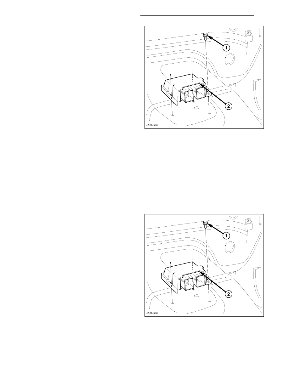
5. Remove the three mounting screws (1) to the ORC

(2).

INSTALLATION

WARNING: Do not install ORC if mounting location is deformed or damaged. This will cause the ORC to be
improperly located and could result in occupant personal injury or death.

WARNING: Never replace both the Occupant Restraint Controller (ORC) and the Occupant Classification
Module (OCM) at the same time. If both require replacement, replace one, then perform the Airbag System
test (Refer to 8 - ELECTRICAL/RESTRAINTS - DIAGNOSIS AND TESTING - AIRBAG SYSTEM) before replac-
ing the other. Both the ORC and the OCM store Occupant Classification System (OCS) calibration data,
which they transfer to one another when one of them is replaced. If both are replaced at the same time, an
irreversible fault will be set in both modules and the OCS may malfunction and result in personal injury or
death.

1. Position the ORC (2) into position and install the

three mounting screws (1). Tighten the screws to
11 N·m (97 in. lbs.).

8O - 402

RESTRAINTS - SERVICE INFORMATION

LX

2. Make sure to reinstall the sound deadening mate-

rial (1) over the ORC.

3. Connect the two electrical connectors (1 and 2).

4. Install the center floor console (Refer to 23 -

BODY/INTERIOR/FLOOR CONSOLE - INSTALLA-
TION).

WARNING: Do not connect the battery negative
cable (Refer to 8 - ELECTRICAL/RESTRAINTS -
DIAGNOSIS AND TESTING - AIRBAG SYSTEM).
Personal injury or death may result if the system
test is not performed first.

LX

RESTRAINTS - SERVICE INFORMATION

8O - 403

PASSENGER AIRBAG

DESCRIPTION

The passenger airbag used in this model is a multi-
stage, Next Generation-type that complies with revised
federal airbag standards to deploy with less force than
those used in some prior models. The passenger air-
bag consists of a stamped and welded metal housing,
the airbag cushion, the airbag inflator, and a stamped
metal airbag cushion retainer plate that is secured to
the airbag housing. The airbag housing contains the
airbag inflator and the folded airbag cushion. A rectan-
gular fabric cushion is used.

The airbag inflator is a non-azide, pyrotechnic-type
unit that is secured to and sealed within the airbag
housing. A short four-wire pigtail harness with a keyed,
yellow connector insulator connects the two inflator ini-
tiators to the vehicle electrical system through the
instrument panel wire harness.

This passenger airbag cannot be repaired, and must
be replaced if deployed, faulty, or in any way
damaged.

The horizontal surface of the injection molded, thermo-
plastic passenger airbag door (2) is the most visible
part of the passenger airbag. The passenger airbag
door is located above the glove box opening on the
top of the instrument panel, in front of the front seat
passenger seating position.

8O - 404

RESTRAINTS - SERVICE INFORMATION

LX

Located below the passenger airbag door within the
instrument panel is the passenger airbag. The passen-
ger airbag housing fits into a molded receptacle on the
back of the airbag door, where twelve stamped hook
formations on the forward and rearward edges of the
airbag housing are engaged in mating small window
openings on the forward and rearward flanges of the
receptacle to secure the airbag door to the airbag
housing. These airbag door fasteners and mounting
provisions are all concealed beneath the instrument
panel base trim.

The passenger airbag is secured by four screws (1)
through a stamped mounting bracket to the instrument
panel cover/pad and two bolts (2) to the instrument
panel structural support.

OPERATION

The multistage passenger airbag is deployed by electrical signals generated by the Occupant Restraint Controller
(ORC) through the passenger airbag squib 1 and squib 2 circuits to the two initiators in the airbag inflator. By using
two initiators, the airbag can be deployed at multiple levels of force. The force level is controlled by the ORC to suit
the monitored impact conditions by providing one of three delay intervals between the electrical signals provided to
the two initiators. The longer the delay between these signals, the less forcefully the airbag will deploy.

When the ORC sends the proper electrical signals to each initiator, the electrical energy generates enough heat to
initiate a small pyrotechnic charge which, in turn ignites chemical pellets within the inflator. Once ignited, these
chemical pellets burn rapidly and produce a large quantity of inert gas. The inflator is sealed to the airbag cushion
and a diffuser in the inflator directs all of the inert gas into the airbag cushion, causing the cushion to inflate. As the
cushion inflates, the passenger airbag door will split at predetermined tear seam lines concealed on the inside sur-
face of the door, then the door will pivot up over the top of the instrument panel and out of the way. Following an
airbag deployment, the airbag cushion quickly deflates by venting the inert gas through vent holes within the fabric
used to construct the back (windshield side) of the airbag cushion. Typically, both initiators are used during an air-
bag deployment event.

LX

RESTRAINTS - SERVICE INFORMATION

8O - 405


Content   ..  747  748  749  750   ..