Chrysler 300/300 Touring/300C, Dodge Magnum. Manual - part 2329


  Index      Chrysler     Chrysler 300/300 Touring/300C, Dodge Magnum - service repair manual


Search            


Content   ..  2327  2328  2329  2330   ..


Chrysler 300/300 Touring/300C, Dodge Magnum. Manual - part 2329


A/C CLUTCH BREAK-IN

After a new A/C compressor clutch has been installed, cycle the compressor clutch approximately 20 times (5 sec-
onds on, then 5 seconds off). During this procedure, set the A/C-heater controls to the A/C Recirculation Mode, the
blower motor in the highest speed position, and the engine speed at 1500 to 2000 rpm. This procedure (burnishing)
will seat the opposing friction surfaces and provide a higher compressor clutch torque capability.
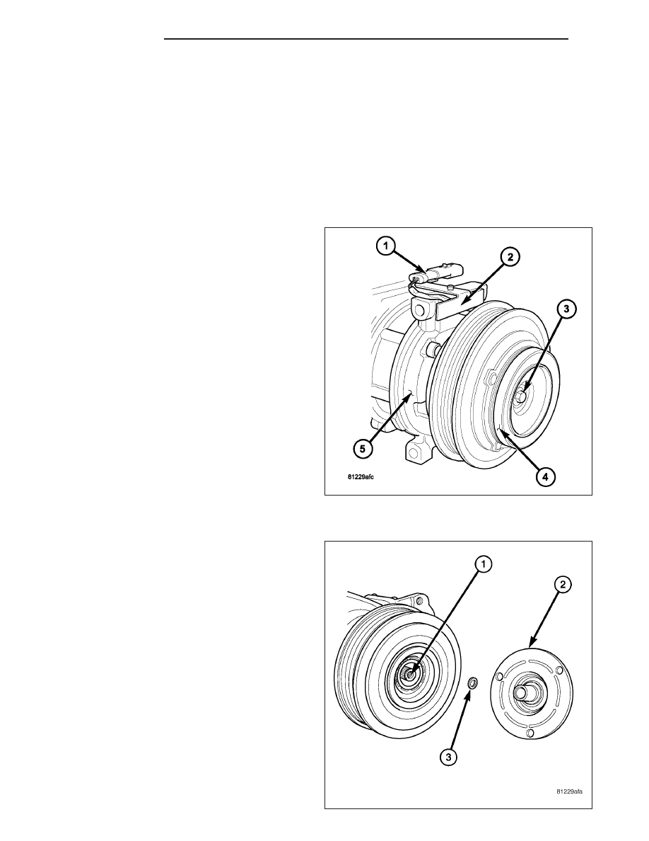
REMOVAL

NOTE: The compressor clutch assembly can be serviced with the refrigerant system fully-charged.

NOTE: Typical A/C compressor shown in illustrations.

1. Disconnect and isolate the negative battery cable.

2. Remove the accessory drive belt (Refer to 7 -

COOLING/ACCESSORY

DRIVE/BELTS-DRIVE

-

REMOVAL).

3. Disconnect the engine wire harness from the com-

pressor clutch field coil connector (1) located on
the top of the A/C compressor (5).

NOTE: Some models (depending on engine appli-
cation) may require the A/C compressor to be
removed from its installed location to gain access
to the compressor shaft bolt and/or pulley and
field coil snap rings. However, the refrigerant sys-
tem can still remain fully charged.

4. If required, remove the bolts that secure the A/C

compressor to the engine and support the A/C
compressor.

5. Carefully remove the compressor clutch field coil

connector and wire lead from the connector bracket
(2).

6. Remove the compressor shaft bolt (3). A band-type

oil filter wrench or a strap wrench may be used to hold the clutch plate (4) from rotating during bolt removal.

CAUTION: Do not pry between the clutch plate and
the pulley and bearing assembly to remove the
clutch plate from the compressor shaft as this
may damage the clutch plate.

NOTE: Use care not to lose any clutch shim(s)
during removal of the clutch plate, as they may be
reused during the clutch plate installation process.

7. Tap the clutch plate (2) lightly with a plastic mallet

to release it from the splines on the compressor
shaft (1) and remove the clutch plate and shim(s)
(3).

24 - 350

CONTROLS

LX

8. Using snap ring pliers (2), remove the snap ring (1)

that secures the pulley and bearing assembly (3) to
the front of the A/C compressor and remove the
pulley and bearing assembly.

9. Using snap ring pliers (1), remove the snap ring (4)

that secures the compressor clutch field coil (2) to
the front of the A/C compressor (3) and remove the
field coil.

INSTALLATION

NOTE: Typical A/C compressor shown in illustrations.

LX

CONTROLS

24 - 351

1. Align the dowel pin on the back of the compressor

clutch field coil (2) with the hole in the front of the
A/C compressor (3) and position the field coil onto
the compressor. Be certain that the compressor
clutch field coil wire lead is properly routed so that
it is not pinched between the A/C compressor and
the field coil.

CAUTION: The snap ring must be fully and prop-
erly seated in the groove or it will vibrate out,
resulting in a clutch failure and severe damage to
the A/C compressor.

NOTE: A new snap ring must be used to secure
the compressor clutch field coil to the A/C com-
pressor. The bevel side of the snap ring must face
outward and both snap ring eyelets must be ori-
ented to the right or to the left of the field coil
dowel pin location on the A/C compressor.

2. Using snap ring pliers (1), install the snap ring (4)

that secures the compressor clutch field coil to the
front of the A/C compressor. Be certain that the snap ring is fully and properly seated in the groove and oriented
correctly.

CAUTION: Be certain to position the compressor
clutch field coil wire lead so that it is not damaged
during A/C compressor pulley and bearing instal-
lation.

CAUTION: When installing the pulley and bearing
assembly, DO NOT mar the friction surfaces of the
pulley or premature failure of the clutch will result.

3. Install the pulley and bearing assembly (1) onto the

front of the A/C compressor. If necessary, tap the
pulley gently with a block of wood (2) placed on the
pulley friction surface.

24 - 352

CONTROLS

LX

CAUTION: The snap ring must be fully and prop-
erly seated in the groove or it will vibrate out,
resulting in a clutch failure and severe damage to
the A/C compressor.

NOTE: A new snap ring must be used to secure
the pulley and bearing assembly to the A/C com-
pressor. The bevel side of the snap ring must face
outward.

4. Using snap ring pliers (2), install the snap ring (1)

that secures the pulley and bearing assembly (3) to
the front of the A/C compressor. Be certain that the
snap ring is fully and properly seated in the groove.

5. If the original clutch plate (2) and pulley and bear-

ing assembly are to be reused, reinstall the original
shim(s) (3) onto the compressor shaft (1). If a new
clutch plate and pulley and bearing assembly are
being used, install a trial stack of shims 2.54 mm
(0.010 in.) thick onto the compressor shaft.

LX

CONTROLS

24 - 353


Content   ..  2327  2328  2329  2330   ..