Chrysler 300/300 Touring/300C, Dodge Magnum. Manual - part 1839


  Index      Chrysler     Chrysler 300/300 Touring/300C, Dodge Magnum - service repair manual


Search            


Content   ..  1837  1838  1839  1840   ..


Chrysler 300/300 Touring/300C, Dodge Magnum. Manual - part 1839


1. Position the front wheels straight-ahead.

2. Fully extend or pull out adjustable steering column.

3. Disconnect the negative (ground) cable from the

battery.

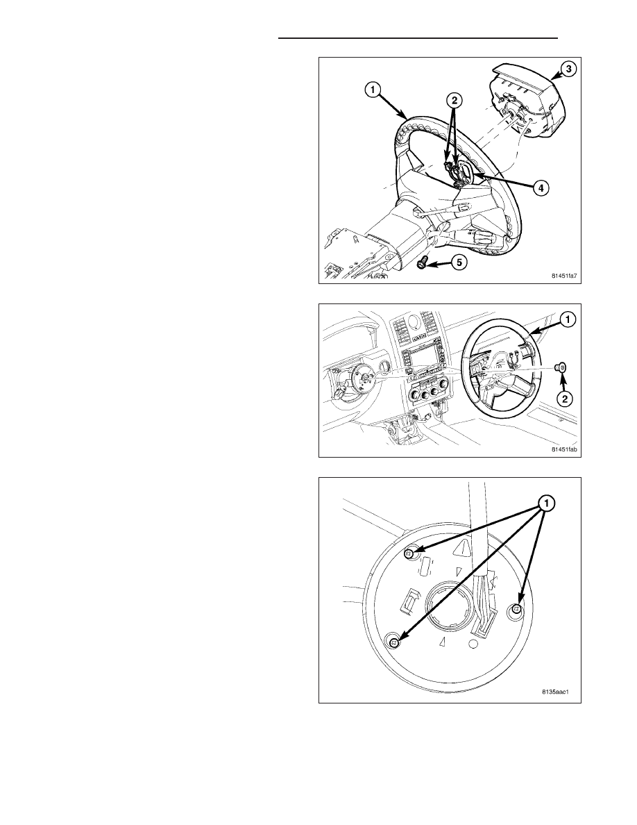
4. Remove the driver airbag (3). (Refer to 8 - ELEC-

TRICAL/RESTRAINTS/DRIVER

AIRBAG

-

REMOVAL)

5. Remove the steering wheel retaining bolt (2), then

slide the steering wheel (1) off the shaft.

6. Unscrew at least one clockspring screw (1) but

don’t take it all the way out, This will help keep the
clockspring from uncentering itself.

19 - 174

COLUMN SERVICE INFORMATION

LX

7. Back out the set screw (1) through the access hole

(3) in the bottom of the Steering Column Control
Module (SCCM) (2).

8. Pull the SCCM (1) off the steering column shaft.

9. To service the individual components contained within the SCCM, (Refer to 19 - STEERING/COLUMN/STEER-

ING COLUMN CONTROL MODULE - DISASSEMBLY).

LX

COLUMN SERVICE INFORMATION

19 - 175

DISASSEMBLY

1. Loosen the three clockspring screws (1) just far

enough to release the clockspring from the SCCM.
Leave them in the clockspring so it won’t unwind.

2. Carefully pull straight up on clockspring to remove.

NOTE: After the clockspring is removed, there is
only one more screw on the top side of the SCCM
that needs to be removed and is located at
approximately the six o’clock position on the
SCCM. It holds the lower side of the steering angle
sensor, the lower side of the electric tilt lever
assembly,

or

the

strengthening

strut

if

not

equipped with electric tilt.

3. If equipped with ESP, remove the steering angle

sensor screw located at the six o’clock position on
the SCCM and remove the steering angle sensor
(1) from the SCCM (2). If not equipped with ESP,
there will be a plastic insert there for strengthening
of the SCCM that will lift right out.

19 - 176

COLUMN SERVICE INFORMATION

LX

4. If equipped with manual telescoping column,

remove the strut screw, located at the six o’clock
position, and strut (1).

5. If equipped with electronic telescoping column,

remove the one remaining screw (4) to electric tilt
located at the six o’clock position, and remove stalk
and switch (3).

LX

COLUMN SERVICE INFORMATION

19 - 177


Content   ..  1837  1838  1839  1840   ..