Chrysler 300/300 Touring/300C, Dodge Magnum. Manual - part 1696


  Index      Chrysler     Chrysler 300/300 Touring/300C, Dodge Magnum - service repair manual


Search            


Content   ..  1694  1695  1696  1697   ..


Chrysler 300/300 Touring/300C, Dodge Magnum. Manual - part 1696


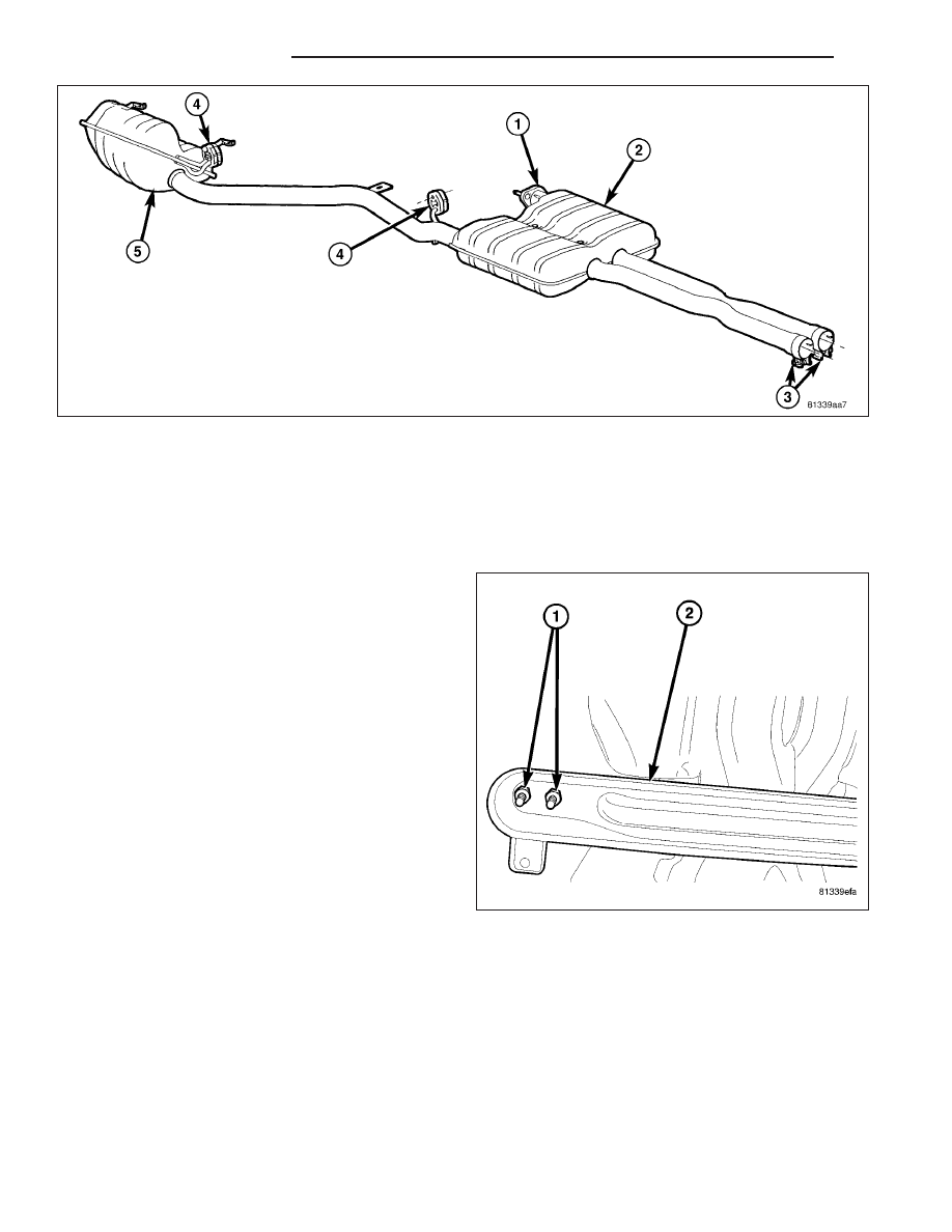
4. 5.7L/6.1L Engine - Install LH rear resonator and tailpipe assembly (Refer to 11 - EXHAUST SYSTEM/RESONA-

TOR - INSTALLATION).

NOTE: Check for proper alignment and clearance to underbody and engine compartment components
before tightening clamps.

5. Tighten band clamps to 61 N·m (45 ft. lbs.).

6. Install tunnel reinforcement (2) and nuts (1).

Tighten nuts to 25 N·m (215 in. lbs.)

7. Check clearance between muffler and resonator

assembly and fuel tank. Clearance is 14mm (.55
in.) for V8 engine and 16mm (.62 in.) for V6
engine.

8. Check clearance at rear tunnel reinforcement.

Clearance is 15 - 20mm (.59 - .78 in.).

9. The tailpipe should be centered in the rear fascia

opening.

10. Adjust clearance as necessary.

11. Lower vehicle.

12. Start the engine and inspect for exhaust leaks.

Repair exhaust leaks as necessary.

11 - 18

EXHAUST SYSTEM

LX

RESONATOR - 5.7L

REMOVAL

WARNING: THE NORMAL OPERATING TEMPERA-
TURE OF THE EXHAUST SYSTEM IS VERY HIGH.
THEREFORE,

NEVER

WORK

AROUND

OR

ATTEMPT

TO

SERVICE

ANY

PART

OF

THE

EXHAUST SYSTEM UNTIL IT IS COOLED. SPECIAL
CARE

SHOULD

BE

TAKEN

WHEN

WORKING

NEAR THE CATALYTIC CONVERTER. THE TEM-
PERATURE OF THE CONVERTER RISES TO A
HIGH LEVEL AFTER A SHORT PERIOD OF ENGINE
OPERATION TIME.

1. Raise vehicle.

2. Remove two nuts (2).

3. Remove isolators (1).

4. Remove LH resonator and tailpipe assembly (5).

INSTALLATION

1. Position LH resonator and tailpipe assembly (5) in

vehicle.

2. Install isolators (1).

3. install ball flange nuts (2). Tighten nuts finger tight.

4. Check clearance between muffler and tailpipe

assembly and fuel tank. Clearance is 14mm (.55
in.) for V8 engine and 16mm (.62 in.) for V6
engine.

5. Check clearance at rear tunnel reinforcement.

Clearance is 15 - 20mm (.59 - .78 in.).

6. The tailpipe should be centered in the rear fascia

opening.

7. Tighten ball flange nuts (2) to 47 N·m (35 ft. lbs.).

8. Lower vehicle.

9. Start the engine and inspect for exhaust leaks.

Repair exhaust leaks as necessary.

LX

EXHAUST SYSTEM

11 - 19

RESONATOR - 6.1L

REMOVAL

WARNING: THE NORMAL OPERATING TEMPERA-
TURE OF THE EXHAUST SYSTEM IS VERY HIGH.
THEREFORE,

NEVER

WORK

AROUND

OR

ATTEMPT

TO

SERVICE

ANY

PART

OF

THE

EXHAUST SYSTEM UNTIL IT IS COOLED. SPECIAL
CARE

SHOULD

BE

TAKEN

WHEN

WORKING

NEAR THE CATALYTIC CONVERTER. THE TEM-
PERATURE OF THE CONVERTER RISES TO A
HIGH LEVEL AFTER A SHORT PERIOD OF ENGINE
OPERATION TIME.

1. Raise vehicle.

2. Remove the bolt (2).

3. Remove isolators (1).

4. Remove LH resonator and tailpipe assembly (5).

INSTALLATION

1. Position LH resonator and tailpipe assembly (5) in

vehicle.

2. Install isolators (1).

3.

install ball clamp bolt (2). Tighten bolt finger tight.

4. Check clearance between muffler and tailpipe

assembly and fuel tank. Clearance is 14mm (.55
in.) for V8 engine.

5. Check clearance at rear tunnel reinforcement.

Clearance is 15 - 20mm (.59 - .78 in.).

6. The tailpipe should be centered in the rear fascia

opening.

7. Tighten ball clamp bolt (2) to 47 N·m (35 ft. lbs.).

8. Lower vehicle.

9. Start the engine and inspect for exhaust leaks.

Repair exhaust leaks as necessary.

11 - 20

EXHAUST SYSTEM

LX

PARTICULATE FILTER

DESCRIPTION

A diesel particulate filter (1) DPF is installed for
exhaust gas after-treatment. The DPF is located
downstream of the main oxidation catalyst (5). The
DPF filters, stores and burns particulate matter (soot)
that is generated during the combustion process. The
soot is oxidized to carbon dioxide CO2 at exhaust
temperatures over 600° C (1,112° F).

OPERATION

The oxidation catalysts raise the exhaust gas temper-
atures to regenerate the DPF (1), which is passive
regeneration. If the passive regeneration cannot keep
up with the build up of soot in the DPF, the ECM will
actively regenerate the DPF to burn off the soot. Res-
idue remains inside the DPF in the form of non burn-
able ash. Ash comes from the oils and other materials
that are trapped in the oils and are present in the
soot. Ash is not eliminated by the regeneration cycle.
Excessive ash accumulation requires the replacement
of the DPF. The DPF uses a silicon carbide wall-flow
monolith with a platinum coating to trap particulates.
The monolith contains a large number of square par-
allel channels, which run in the axial direction and are
separated by thin porous walls. The channels are
alternatively open at one end, but plugged at the
other. The exhaust gases flow through the walls and
escape through the pores in the wall material. Partic-
ulates, however, are too large to escape and are
trapped in the monolith walls. The ECM starts the
regeneration of the DPF if the soot load exceeds a performance map value. The ECM determines the load condition
of the DPF based upon the exhaust gas pressure upstream (2) and downstream (2) of the DPF. A pressure differ-
ential sensor (2) provides the pressure input to the ECM. During the regeneration process, the ECM raises the
temperature in the DPF to burn off the soot accumulated. Under normal operation, the engine does not produce
enough heat to oxidize the soot inside the DPF. This process requires temperatures above 550 °C (1,022 °F). After
regeneration, the ECM reads the actual pressure difference at the DPF and compares it with a reference value.
From this comparison, the ECM determines the ash quantity inside the DPF.

LX

EXHAUST SYSTEM

11 - 21


Content   ..  1694  1695  1696  1697   ..