Chevrolet Silverado / GMC Sierra. Manual - part 863
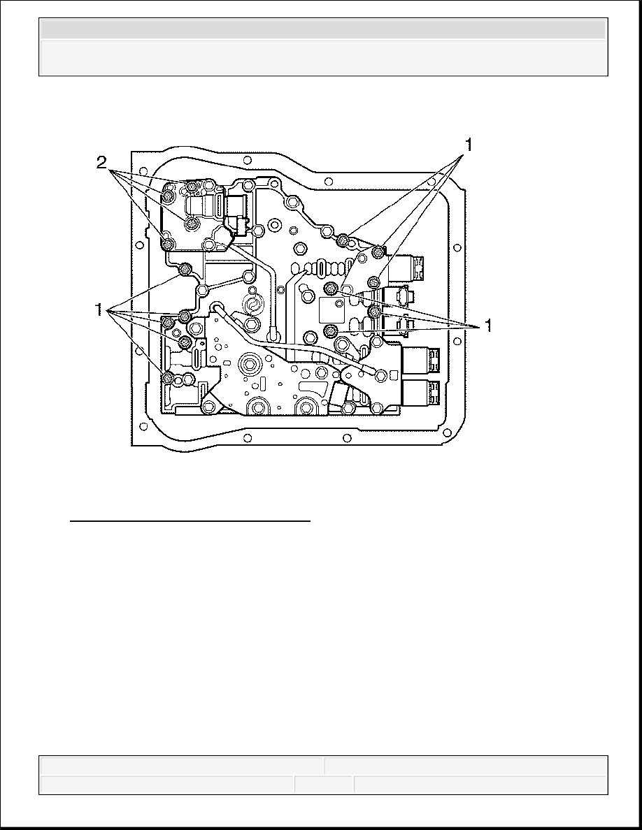
Fig. 80: Control Valve Assembly Bolts
Courtesy of GENERAL MOTORS CORP.
8. Remove 10 bolts at locations marked (1) and 4 bolts at locations marked (2). Support the
control valve assembly, about 10 pounds, and remove the last bolt marked (1).
IMPORTANT: As the control valve assembly is removed, be careful not to
lose the manual selector valve pin or allow the manual
selector valve to slide out of the control valve assembly.
2008 Chevrolet Silverado 1500
2008 TRANSMISSION Automatic Transmission - Allison - Cab & Chassis Sierra, Cab & Chassis Silverado, Sierra &
Silverado
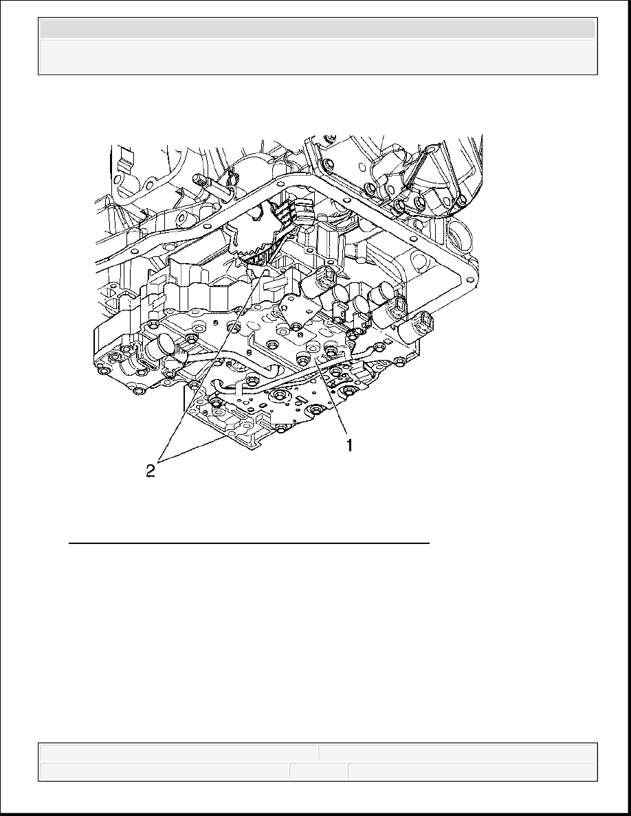
Fig. 81: View Of Control Valve Assembly & Locating Pins
Courtesy of GENERAL MOTORS CORP.
9. Lower the control valve assembly (1) to clear the locating pins (2) in the transmission case.
2008 Chevrolet Silverado 1500
2008 TRANSMISSION Automatic Transmission - Allison - Cab & Chassis Sierra, Cab & Chassis Silverado, Sierra &
Silverado

Fig. 82: Moving Control Valve Assembly Sideways To Clear Manual Selector Valve
Courtesy of GENERAL MOTORS CORP.
10. Move the control valve assembly (4) sideways to disengage pin (1) in the manual selector
valve (2) from the slot in detent lever (3). Remove the control valve assembly (4).
Installation Procedure
2008 Chevrolet Silverado 1500
2008 TRANSMISSION Automatic Transmission - Allison - Cab & Chassis Sierra, Cab & Chassis Silverado, Sierra &
Silverado
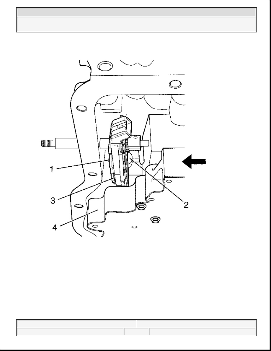
Fig. 83: Positioning Control Valve Assembly To Engage Manual Selector Valve Pin
Courtesy of GENERAL MOTORS CORP.
1. Move the control valve assembly (4) into position under the transmission case. Engage the
pin (1) in the manual selector valve (2) into the slot in the detent lever (3).
2008 Chevrolet Silverado 1500
2008 TRANSMISSION Automatic Transmission - Allison - Cab & Chassis Sierra, Cab & Chassis Silverado, Sierra &
Silverado