Chery Tiggo 5 (T21). Manual - part 434
38–
17
38
DTC
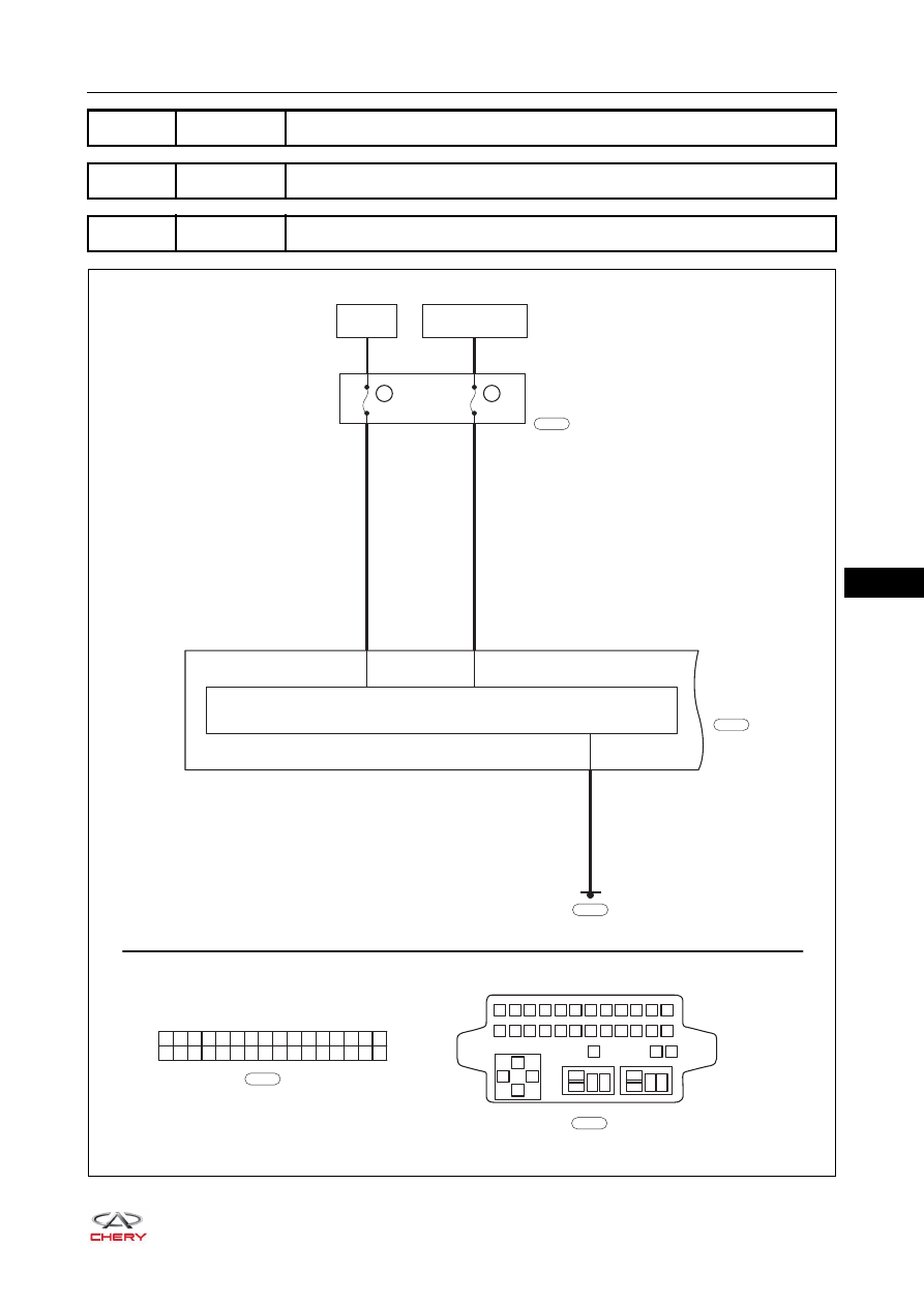
B1100-13 Power Supply Circuit Open
DTC
B1100-16 Power Supply Circuit Voltage Below Threshold
DTC
B1100-17 Power Supply Circuit Voltage Above Threshold
ET21380050
BATTERY
R
P
RF23
10A
INSTRUMENT
CLUSTER
23
10A
RF06
6
11
13
1
2
3
4
5
6
7
8
9 10 11 12
13
85
85
87
87 30
87 30
30
86
86
85
86
14 15 16 17 18 19 20 21 22 23 24
25
27
26
IGNITION SWITCH
ON OR START
32
31
30
29
28
16
15
14
13
12
11
10
9
8
7
6
5
4
3
2
1
27
26
25
24
23
22
21
20
19
18
17
INSTRUMENT
PANEL
FUSE AND
RELAY BOX A
B
I-007
I-007
L
I-015
I-015
MICROPROCESSOR
I-003
3
B