Chery Tiggo 5 (T21). Manual - part 405
36–
3
36
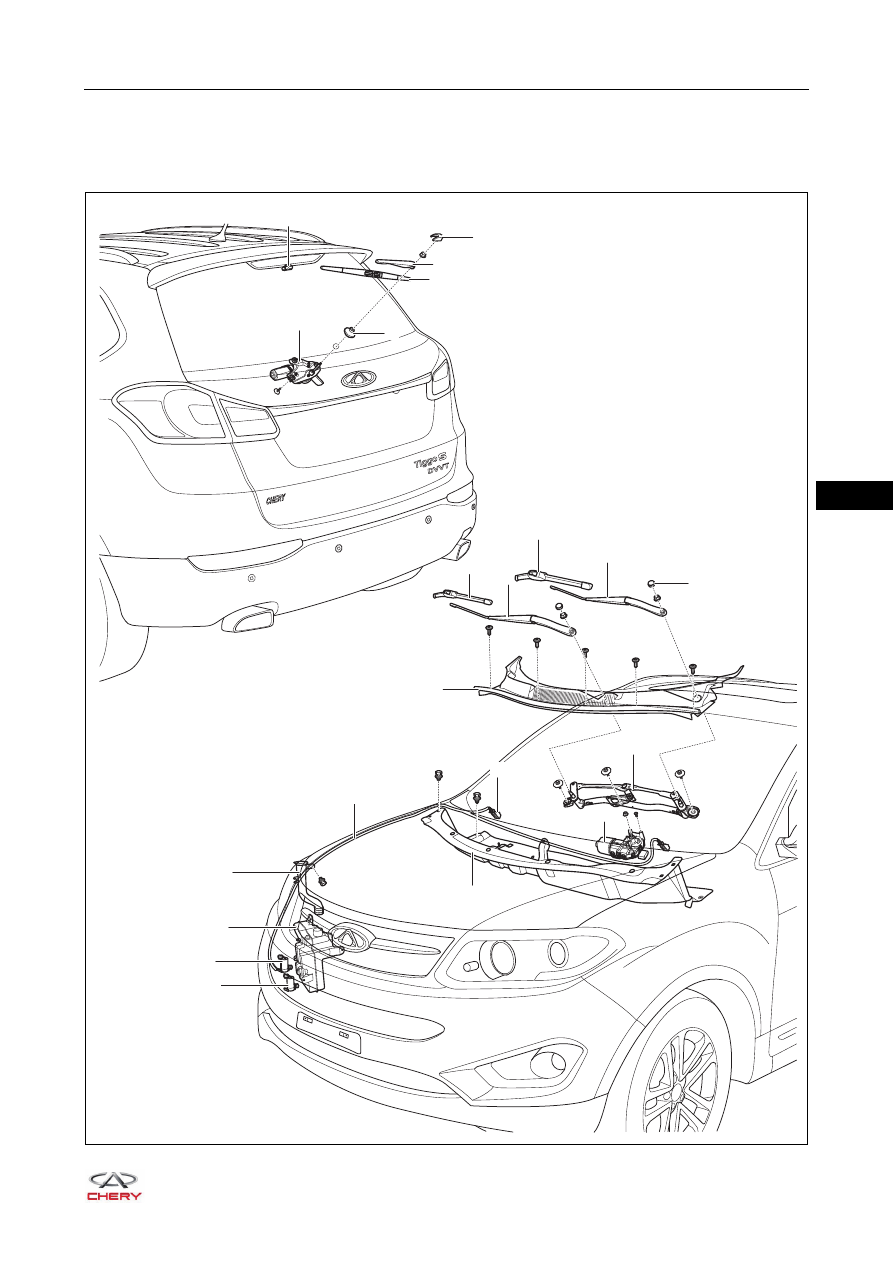
GENERAL INFORMATION
Description
RT21360010
×12
×2
×4
×3
×3
6
2
3
1
9
8
7
5
4
14
13
17
15
10
11
16
12
18
19
20
21
|
|
|
36– 3 36 GENERAL INFORMATION Description RT21360010 ×12 ×2 ×4 ×3 ×3 6 2 3 1 9 8 7 5 4 14 13 17 15 10 11 16 12 18 19 20 21 |