Chery Tiggo 5 (T21). Manual - part 320
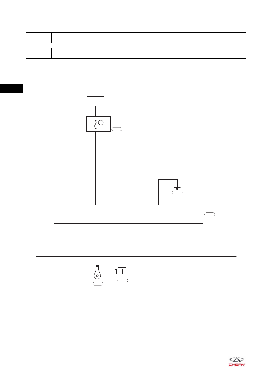
30–
12
30
DTC
C1901
Battery Under Voltage Error
DTC
C1902
Battery Over Voltage Error
ET21300020
BATTERY
R
B
MF09
80A
A1
EPS
A2
L
E-077
A1
A2
E-077
E-081
E-064
EPS
POWER
E-064
|
|
|
30– 12 30 DTC C1901 Battery Under Voltage Error DTC C1902 Battery Over Voltage Error ET21300020 BATTERY R B MF09 80A A1 EPS A2 L E-077 A1 A2 E-077 E-081 E-064 EPS E-064 |