Chery Tiggo 5 (T21). Manual - part 260


  Index      Chery     Chery Tiggo 5 (T21) - service repair manual 2014 year


Search            


Content   ..  258  259  260  261   ..


Chery Tiggo 5 (T21). Manual - part 260


23–

35

23

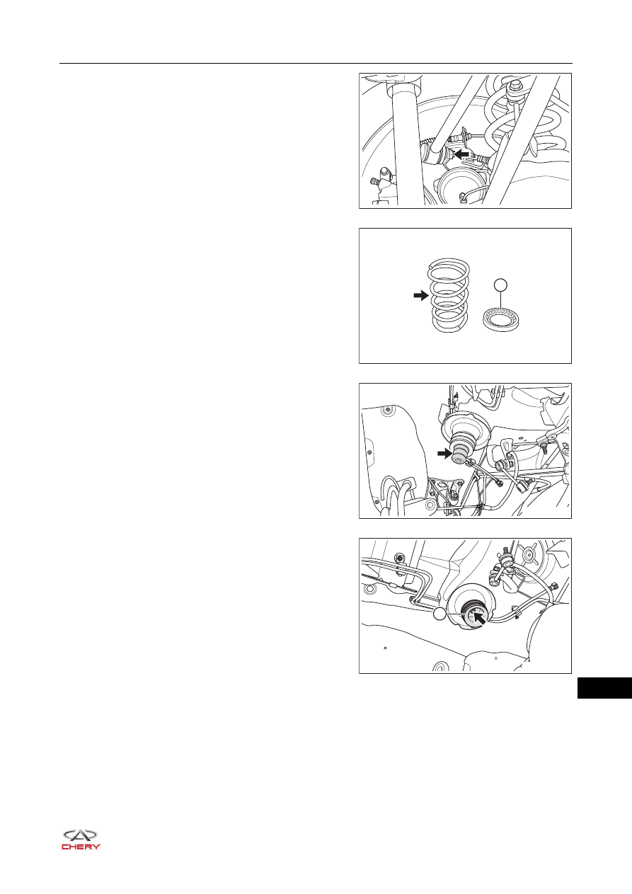
e. Remove the coupling bolt and nut (arrow) between 

lower part of rear suspension upper left swing arm 
assembly and rear left trailing arm assembly.

(Tightening torque: 120 ± 10 N·m)

f. Lower the transmission carrier slowly to the 

appropriate height and take off the rear coil spring 
(arrow) and rear spring upper cushion (1) carefully.

g. Detach the rear buffer block (arrow) from the body.

h. Remove the fixing bolt (arrow) and detach the rear 

rubber cushion assembly (1) from body.

(Tightening torque: 25 ± 5 N·m)

RT21230400

1

RT21230410

RT21230420

RT21230430

1

23–

36

23

Inspection

1. Check rear coil spring assembly.

a. Check rear coil spring for wear, cracks and permanent deformation due to excessive use. Replace as 

necessary.

b. Check rear coil spring upper cushion, rear cushion and rear rubber cushion assembly for dirt, wear, 

cracks, deformation or damage. Replace as necessary.

Installation

Installation is in the reverse order of removal.

CAUTION

 Always tighten coupling bolts and nuts to the specified torque.
 After installation is completed, lower vehicle and bounce it up and down several times to stabilize the 

suspension.

23–

37

23

Rear Suspension Upper Swing Arm Assembly

Removal

HINT:

 Use the same procedures for the right side and left side.

 Procedures listed below are for the left side.
1. Remove the rear left wheel (

See page 24-9

).

2. Remove the rear suspension upper left swing arm assembly.

a. Remove the coupling bolt and nut (arrow) between 

lower part of rear suspension upper left swing arm 
assembly and rear left trailing arm assembly.

(Tightening torque: 120 ± 10 N·m)

b. Remove the coupling bolt and nut (arrow) between 

upper part of rear suspension upper left swing arm 
assembly and rear sub frame assembly.

(Tightening torque: 120 ± 10 N·m)

c. Remove the rear suspension upper left swing arm assembly.

Installation

Installation is in the reverse order of removal.

CAUTION

 Be sure to wear necessary safety equipment to prevent accidents.
 Make sure that safety lock of lifter has been locked when removing and installing chassis parts.
 It is not permitted to weld or modify suspension bearing parts.
 When removing and installing chassis parts, replace self-locking nuts and rusted nuts for safety.

RT21230400

RT21220330

CAUTION

 Always tighten coupling bolts and nuts to the specified torque.

23–

38

23

Rear Suspension Lower Swing Arm Assembly

Removal

HINT:

 Use the same procedures for the right side and left side.

 Procedures listed below are for the left side.
1. Remove the rear left wheel (

See page 24-9

).

2. Remove the rear suspension lower left swing arm assembly.

a. Remove the coupling nut (arrow) between lower part 

of rear left stabilizer link assembly and rear 
suspension lower left swing arm assembly.

(Tightening torque: 45 ± 5 N·m)

b. Remove 2 coupling bolts (arrow) between rear left 

shock absorber assembly fixing bracket and rear left 
trailing arm assembly.

(Tightening torque: 80 ± 8 N·m)

c. Remove the coupling bolt and nut (arrow) between 

lower part of rear suspension lower left swing arm 
assembly and rear left trailing arm assembly.

(Tightening torque: 120 ± 10 N·m)

CAUTION

 Be sure to wear necessary safety equipment to prevent accidents.
 Make sure that safety lock of lifter has been locked when removing and installing chassis parts.
 It is not permitted to weld or modify suspension bearing parts.
 When removing and installing chassis parts, replace self-locking nuts and the rusted nuts for safety.

RT21230370

RT21230380

RT21230390


Content   ..  258  259  260  261   ..